I’d been complaining about headphone wiring and computer audio-quality issues quite a bit recently. Someone must have gotten tired of hearing me complain, because I was given a FiiO E07K Andes headphone amplifier for my birthday. It is a nice little piece of hardware that can be used as a high-quality USB sound device. It sounds excellent, and I can’t hear even the faintest hint of static through my headphones.

The trouble was that I needed to put it somewhere within reach of my short headphone cable. My quick and dirty solution was to use some poster tack to stick it to the right-hand side of my desk. It was easy to arrive at this solution, because that’s exactly what I was already doing with the small microphone adapter box that came with my headphones.
This worked, but you can see that it was an ugly solution. I have a 3D printer, so I figured I should be able to come up with a better solution. I wanted to make some sort of case that I could slide the FiiO Andes amplifier right into, and I thought it would be nice if it could also hold on to my microphone extension cable for me.
It took me three iterations to finally print the mount that I am using right now. This seems to be par for the course so far for my attempts at 3D design.
Using OpenSCAD instead of Blender
Blender lets you create shapes and modify them vertex by vertex, so it is very flexible. It is also a pain in the neck to design anything which requires very precise and specific measurements. Good luck adjusting your model if you print a part and learn that an opening is just a fraction of a millimeter too wide.
When you use OpenSCAD, you have to build your model pragmatically from basic shapes, and you can store all your dimensions in variables. It took me longer to get going, but being able to make minute adjustments to your measurements without having to manually manipulate the model is well worth the extra effort up front.
1 2 3 4 5 6 7 8 9 | |
After my first print, I realized the mount was too loose, and the tabs at the top weren’t quite wide enough to hold the FiiO in place. All I had to was adjust the width and tabwidth variables, and the whole model rebuilt itself based on the new dimensions. In fact, I could easily reuse this OpenSCAD file to build a case or mount for just about anything, like a phone or a tablet.
The first attempt
I was really amazed with how well the first mount came out. It was a little too boxy—I hadn’t figured out how to make bevels like I could in Blender, and it was pretty loose. The FiiO amplifier could slide around quite a bit, and the tabbed overhangs at the top were very narrow. You could just about lift the FiiO right out of the top with a bit of force.


I could have stopped right here, though. I had already screwed this mount to the desk, and it was working just fine. The microphone extension holder worked perfectly, which was a huge surprise to me. It is a little snug, but I was able to snap the connector and cable into the slot with just a bit of force.
The channels in the bottom of the mount lined up perfectly with the rubber feet on the bottom of the amplifier, and they were just deep enough. I’m getting pretty good at measuring things accurately with my caliper.
The second attempt
I learned quite a bit from the first print, and I made some significant improvements to the design. I found the MCAD library on GitHub, and it has a handy “rounded box” function. I replaced the biggest “cube” in my design with a combination of two rounded boxes, but it wasn’t as straight-forward as I hoped it would be. It worked out in the end, and now my mount has some nice rounded edges and corners.


I also added two small bump stops to the front of the case. They’re supposed to be the top half of a pair of spheres, but they printed like two tiny cylinders. They still work great, and they keep the FiiO amplifier from sliding out on its own. The mount was still too long, so the amplifier could slide back and forth quite a bit.
I increased the width of the overhangs on the top by quite a bit. I bumped them up to 2.5 mm. This is more than wide enough to keep the FiiO amplifier from falling out, but still narrow enough that the first overhanging layer doesn’t sag too badly. I also carved out a channel in each side for the FiiO’s buttons to pass through. They were rubbing quite a bit on the first mount.
I should have cleaned up the sagging material before trying to slide the FiiO unit into the mount. The combination of this extra material and my impatience caused one of the tabs on the front to snap off. Even without this tab, the case was still a much better fit than the first one.
I also messed up the microphone extension holder. I moved the holder towards the back of the mount to get it out of the way of the beveled edges, but I quite literally only moved the holder. I didn’t move the model of the microphone extension back with it. That meant that when I subtracted the microphone extension from the “cube,” it just didn’t quite line up anymore, and it couldn’t hold the cable nearly as well. This was simple to fix in the final print.
OpenSCAD doesn’t always catch your mistakes
The version of OpenSCAD that I’m using is a few releases behind. The new version lets you specify the diameter or radius of spheres and cylinders. The version I’m running only allows you to specify the radius.
I accidentally supplied a diameter for the cylinders I’m using for the screw holes. OpenSCAD still gave me two cylinders, but they were too narrow. They seemed a bit tight, but they worked, so I assumed that I measured wrong.
I fixed this in the final design, and added some room so I could cleanly countersink my screws. These new screw holes work much better than the broken ones!
OpenSCAD also lets you use misspelled variable names. It will still generate the shape you’re looking for, but it won’t be the correct size. This was difficult to debug on more than one occasion.
The finished product
I only made minor adjustments before the final print. I measured how far the amplifier could side while in the mount, and I subtracted that from the length of the mount. You’ll probably be as surprised as I was to learn that I measured this perfectly. When you push the FiiO unit into place, it goes past the bump stops with a satisfying thump. Once it is in place, it doesn’t move at all!

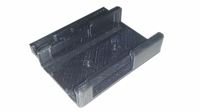
I also made the gaps on the sides as narrow as I could. They need to be wide enough so that I can get to the buttons, but I was able to add 3 mm to the fragile front tabs. I hoped this would help, but I ended up breaking the opposite tab on the final version of the mount while I was recording the video.
I’m still using the mount with the broken tab. The FiiO E07K still fits nicely, and it isn’t going to fall out. I won’t be printing a replacement unless I think of a better solution to the problem.
The walls of this mount are already pretty thick—3 mm thick. I did weaken them a little when I made enough room so that the buttons wouldn’t get hung up on the sides, and it would probably help if I compensated for that. I don’t really want to do that, because the screw holes would move.
That would mean that I’d have to put more screw holes into my desk. I’m definitely willing to do that—there are already quite a few holes in the legs—but the mount is still very solid even with the missing tab.
Final thoughts on OpenSCAD and my OpenSCAD source code
I’m extremely happy with OpenSCAD and will probably be using it for every functional 3D model I create in the future. I am unhappy with the state of the source code for my FiiO mount, and it is more than a little embarrassing to share it with you.
Things started off so well. I had nice definitions for the dimensions of the FiiO E07K, and I built up the walls of the mount by adding my “thickness” variable to those dimensions. A few steps later, things started to get more complicated and a little weird. Sometimes I was adding or subtracting that “thickness” variable, or double the “thickness,” or half.
Sometimes it made sense. Sometimes it didn’t. I wasn’t planning ahead. I was just trying things to see how they would render. This made for some very haphazard and ugly math that should definitely be refactored and cleaned up.
- FiiO E07K Andes USB DAC at Amazon
- FiiO E07K Mount model at GitHub
- FiiO E07K Mount model at Thingiverse
- Microphone Extension Cable at Amazon