I’ve been working on my biggest, most complicated OpenSCAD part since November. It is a cover to hide the cables coming out of the back of my monitor stand. It feels like a long time to be working on the same print, but I did print out a very successful version of this part back in November. The teeth that were meant to hold it in place worked better than I had anticipated, but my measurements were off by about 4 mm.
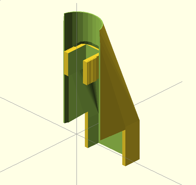
It fit well enough, and I left it on there for about a month. Unfortunately, I knew that it was wrong, so I had to correct the model and print another copy. I was printing the updated part over the weekend, but I had a slipping Y-axis during the first half of the print.
Keep an eye on your belts
I actually noticed the Y-axis belt vibrating around during the print. This belt was one of my biggest problems in the first weeks of owning my Prusa i3 printer. It is just a little too long, and I can’t really get in there to shorten the belt properly without taking the build plate completely apart.
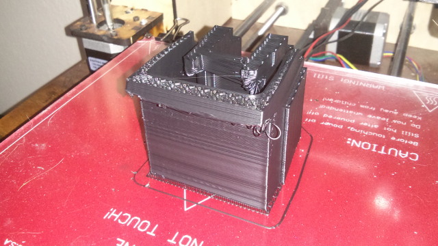
My quick solution was to use the spring from a clothespin as a belt tensioner. It worked very well, but I suspect that the spring has been constantly loosening. I tried to find a way to put tension on the belt while the printer was running, but that wasn’t an easy task. It is hard to make out in the pictures, but I can see how much smoother it is during the section where I was able to add some temporary tension.
After the failed print, I was able to tighten that spring back up. There were two other problems. It was getting too late in the day to start another eight-hour print, and my spool of ABS filament is running low. I don’t know if there is enough material left for such a large object.
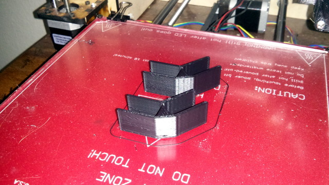
Not wanting to end the day on a failed print, I decided to design something simple.
From zero to printing in less than 45 minutes
I decided to print a pair of brackets to hold my monitors in place. The monitor stand does an excellent job, but the frames of the monitors are made of thin sheet metal. They flex quite a bit if you push on them.
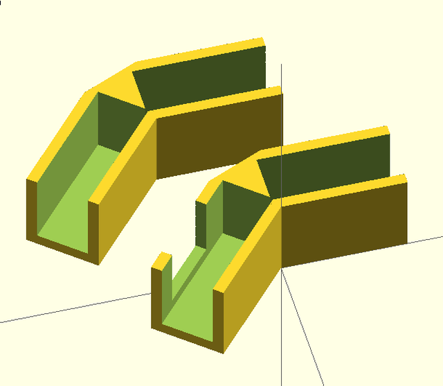
I used my handy angle finder to figure out precisely what angle my monitors are sitting at in relation to each other, and I went to work designing a simple bracket in OpenSCAD. I don’t mean to brag, but I am really impressed with how quickly this process moved along. I was able to clear off the printer, correct the tension on the belt, design the new brackets, and start printing them in less than 45 minutes.
The first set of brackets
The first set of brackets did the job, but they weren’t perfect. The top bracket was a few mm too wide, and it was hitting a bulge in the back of the monitors. I also didn’t know that the power connector for the backlight is in the bottom corner of the monitor, so the bottom bracket wasn’t going to fit over that.
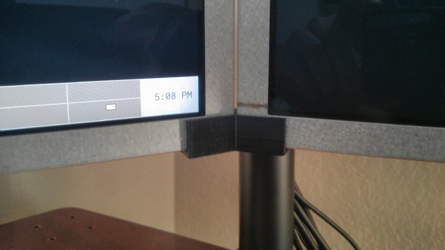
Thankfully, ABS is very east to cut. I just clipped everything down so the brackets would fit, and they did a most excellent job. If I wiggle one monitor around now, they both wiggle in unison. And best of all, they don’t squeak if they rub up against each other!
There was another small issue. The little wedge on the inside of the bracket was keeping the monitors from touching. Clipping some of that wedge out improved things a bit, but the monitors could still only get so close together. At this point, they were roughly 0.1mm apart. That is quite close, but I wanted to improve on that.
The updated set of brackets
Updating the bracket model was easy. I lowered the value of my length variable by a few mm. I also made the length of channel that’s carved out of the bracket a few tenths of a mm longer. This made that troublesome wedge a bit smaller and got it out of the way.
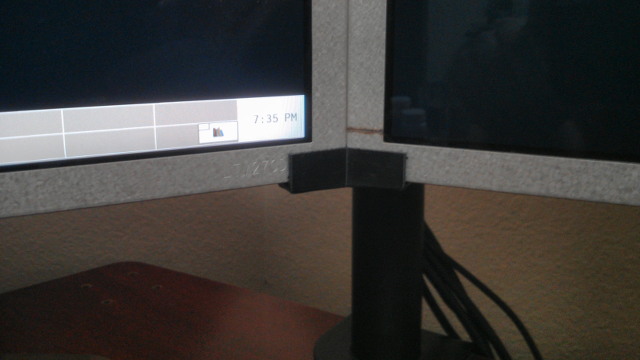
The first set of brackets were identical, but now I needed to leave room for the power connector on one of the brackets. Duplicating the brackets was simple enough. I just moved the bracket into a module—OpenSCAD calls their functions “modules.”
That made it very easy to create a pair of brackets, and to carve a section out of one to make room for the power connector.
They work great—I just wish I didn’t have to look at them
My monitors have never been this close together, and they have never been this stable. I have wished for a setup this solid since I bought my first pair of LCD monitors back in 2001.
I just don’t like the way they look. I like the bare, clean look of the metal frames of my debezeled monitors. I don’t like ruining that with a pair of black plastic bricks. Unfortunately, I don’t think I can have my cake and eat it too.
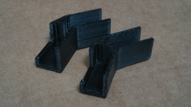
The only other reasonable solutions that I can come up with involve hiding some sort of brackets behind the monitors and attaching them with some sort of adhesive. That would be less than ideal. I like being able to easily move my monitors around. It makes them easier to clean, and it makes it easier to access the connectors and wiring.
I think that I am going to keep using them. This final set of brackets is keeping my monitors ridiculously close together. I can’t even fit my 0.04mm feeler gauge between them. For reference, a dollar bill is around 0.1mm thick.
They’ve been in place for almost a week, and my QX2710 monitors haven’t budged. The brackets are doing a great job of making up for the flimsiness of the monitors’ sheet metal.
- 3D Printed Monitor Bracket at GitHub
- Monitor Bracket for Debezeled QNIX QX2710 Monitors at thingiverse.com