I’ve been contemplating the idea of implementing some home automation for a very long time. The benefits just hadn’t been exciting enough to encourage me to get started. Turning lights on and off didn’t seem all that interesting to me.
A number of small things came together recently that gave me just enough encouragement to start implementing some automation. Every day when I wake up, I make a delicious latte for myself using my Rancilio Silva. It is an excellent machine, but it takes 20 or 30 minutes to get warmed up enough to pull a good shot of espresso.
My home office is upstairs, and my espresso machine is downstairs. I often forget to run downstairs before heading to the office. When I do forget, that means I walk downstairs to a cold espresso machine, and I have to wait at least 20 minutes for my coffee.
Radio Controller Power Outlets
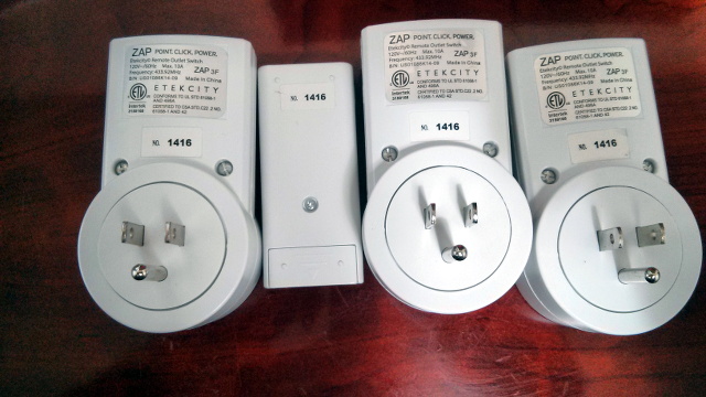
There happened to be a sale on Etekcity RF-controlled power outlets at Amazon one day. I found an article on hackaday.io explaining how to control these AC outlets using an Arduino. I had already been messing around with ESP-01 WiFi dev boards for a while, and I knew how easy it was to load Arduino sketches on them.

I immediately ordered a 3-pack of Etekcity remote-controlled power outlets. Building a little WiFi to 433 MHz RF bridge seemed like a good idea, and the 3-pack of Etekcity outlets was about half the price of a single Belkin WeMo outlet. How could I beat that?
- Etekcity ZAP Power Outlets at Amazon
Reading the RF codes with an Arduino
I found a write-up over at Hackaday.io about controlling these Etekcity power outlets using an Arduino. He is using the RCSwitch Arduino library to communicate with his Etekcity power outlets, and it turns out the RCSwitch library is very simple to use.
RCSwitch ships with an example sketch named ReceiveDemo_Advanced. All you have to do is wire up an inexpensive RF 433 MHz receiver to your Arduino, and upload this sketch. Then you just start hitting buttons on your Etekcity remote control, and the remote control codes will be printed on the Arduino’s serial port.
I completed this part of the project before any of my ESP8266 boards arrived. I just plugged an RF receiver into on of my Arduino boards, hit all the buttons on my Etekcity remote control, and made a note of the codes.
- RCSwitch – How To Recieve wiring diagram
- Voice Controlled Outlets at Hackaday.io
Transmitting the RF codes with an Arduino
Testing the codes and RF transmitter was even easier than reading the codes from the remote. The RCSwitch library also comes with a sketch named SendDemo. I just added codes corresponding to my own Etekcity power outlets to the demo.
I wired the RF transmitter to the Arduino and uploaded the sketch, and I plugged my IKEA floor lamp into one of the Etekcity outlets. When the Arduino booted back up, the power outlet began turning on and back off once every couple seconds.
This was pretty exciting for me. That lamp was the biggest real-world device I’ve ever controlled with an Arduino!
- RCSwitch Arduino Library at GitHub
The Node.IT ESP210 is awesome
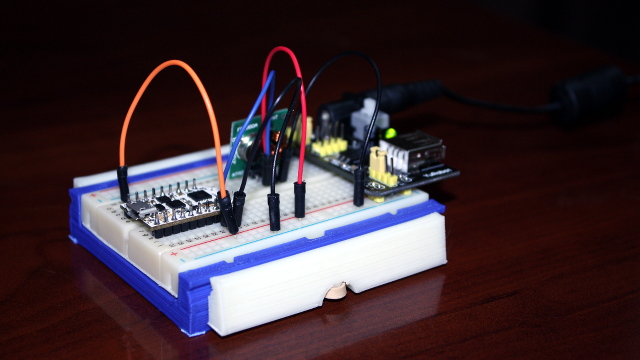
I started this project with an ESP-12 on a cheap breakout board adapter. The ESP-12 boards work great, and they are ridiculously inexpensive. Unfortunately, they’re a real pain in the neck during development. I hate having to connect four or five wires to my USB FTDI every time I need to upload new code. Those big, cheap breakout boards for the ESP-12 are kind of a nuisance, too. They’re just too wide to be used conveniently with a breadboard!

The fine folks at Electronic Sweet Peas were kind enough to send me a couple of preproduction models of their wonderful little ESP210 boards. The ESP210 is an ESP8266-based dev board with an integrated USB to serial chip and a voltage regulator. I don’t know how they did it, but they managed to squeeze those two major upgrades and all the pins of an ESP-12 onto a board nearly as tiny as the ESP-01!
It was a piece of cake to pull the ESP-12 out of my prototype and swap in the ESP210 in its place. I was able to upload the code without making any changes, and it worked perfectly!
The ESP210 isn’t just another ESP8266 development board. It is part of the Node.IT family of tiny, modular add-on boards called “+One” modules that plug into the ESP210 board. There are +One modules that offer things like a real-time clock, additional analog or digital GPIO pins, and even humidity sensors or Micro SD card slots.
- ESP-12 module at Amazon
- Node.IT ESP210 module at Sweet Peas
How far did this get me?
Pretty far! It was simple enough to control the outlets from the command line using curl, or with browser bookmarks on my phone. Before long, I had the lamp in my office turning off every time Steam launched a game. I was also able to use Tasker on my Android phone to turn on my espresso machine as soon as I unplugged my phone in the morning.
This was a good start, and it gave me some idea of how useful home automation can be. Unfortunately, controlling multiple switches from multiple computers won’t scale very well.
Controlling the ESP8266 to RF bridge with OpenHAB
I’ve since set up an OpenHAB server that lives on my power-efficient virtual machine server. It is doing a great job of controlling my devices and keeping track of what I’m doing.
Creating OpenHAB rules for my Etekcity power outlets was easy. OpenHAB has a sendHttpGetRequest function. I just have to call that function with the correct URL whenever a switch is toggled.
1 2 3 4 5 6 7 8 9 10 11 12 13 | |
I could easily write several thousands words about the things I’ve done so far using OpenHAB. I’ll leave that for future blog posts.
You can find the code for my ESP8266 RF Bridge at Github!
I uploaded a copy of my ESP8266 Wi-Fi to RF433 bridge repository to GitHub. The README file really needs some attention, but other than that, it should be good to go. Just plug the data pin of your RF433 transmitter into GPIO 2, then replace the ssid and password variables with the correct values for your network, upload the sketch to an ESP8266, and you should be ready to go!
- ESP8266WiFiToRF433 at GitHub
- Etekcity RF Power Outlets at Amazon