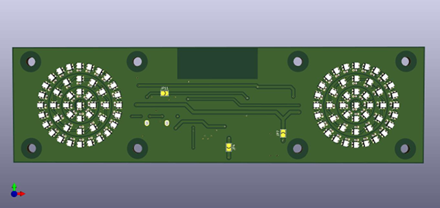
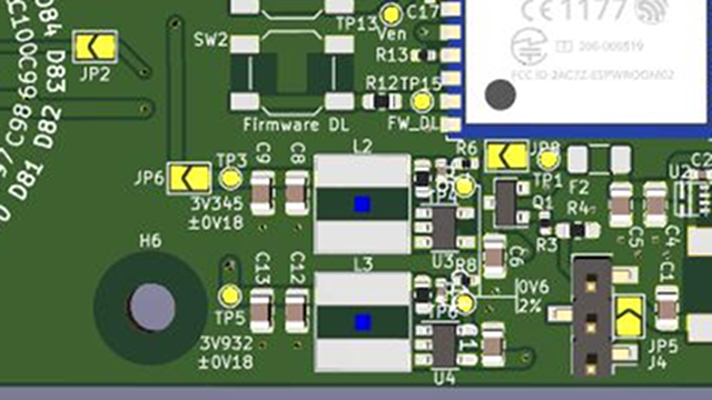
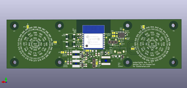
I first posted about this in May. We’ve been working on this for nearly six months. How can that be possible? To me, it feels like we just started talking about the idea a few weeks ago!
Life has been getting in the way. We’ve gone through some redesigns, but things are looking good now. I was handed a copy of all the work today. In theory, I could send this off to have a handful of OoberLights boards manufactured right now. In practice, I’m going to stick these in front of a few eyeballs to make sure everything is really ready to go.
What are OoberLights?
Is one board an OoberLight? Is one board an OoberLight board? Or should it always be plural, because there are lots of lights on the board? Maybe each ring is an OoberLight, and the board with two rings should be referred to as OoberLights? This is something we’ll have to figure out.
I’ve already written about where the idea came from, but I figure I may as well talk about it again. A long time ago, I learned of the existence of dekatrons. I’m pretty sure I saw one or two LED dekatron imitations on hacakday.com. At around the same time, I had also learned of something called charlieplexing.
Finally got the dekatron #tube for the #nixieclock Testing it out now. Works perfectly! #steampunk #clock #time #electronics #diy pic.twitter.com/ATKV2uem2M
— Just Generic (@JustGeneric1) November 5, 2019
With this newfound knowledge, I thought it might be fun to wire up a ring of red LEDs to replace the indicator LEDs on my IBM Model M keyboard. At the time, I didn’t even own a 3D printer. I had no idea how I could ever make something like that look nice, so it never came to fruition.
I chatted with a friend about doing a PCB. I was thinking we’d do one ring of WS2812 RGB LEDs with the intention of putting one or two of these rings into a 5.25” drive bay on my virtual machine server. In that form factor, I believe we would have been able to make a circle of about a dozen LEDs.
Then we thought about doing concentric rings. The 5mm LEDs are pretty big, so the smaller ring isn’t all that circular looking. Then something awesome happened. 2mm WS2812 LEDs started shipping!
If you count the single LED in the center as a ring, we are now able to fit four concentric rings within the height of a 5.25” optical drive bay. There are now 24 LEDs in the outer ring, and a total of 90 LEDs in the pair of rings on the board!
What do you do with something like this?
When the OoberLights were less uber, my ideas were pretty simple. You could send a pixel spinning around the ring at varying speeds to indicate network throughput. You could have pixels spinning in opposing directions to indicate the direction of network traffic. You could light up LEDs like a progress bar to indicate disk usage or CPU load.
Then the OoberLights got a whole lot more uber! We should be able to draw hands like a clock. We will be able to pulse the concentric rings like a raindrop on water. We can have each concentric ring displaying different information. I’d like to be able to have several of these animations running at the same time. The possibilities have gotten quite large!
What if I don’t have 5.25” drive bays? Can I put this on my desk?
The OoberLights board receives 5-volt power via a micro=USB port. We are using an ESP8266 microcontroller to control the LEDs. You will be able to communicate with the Ooberlights using either the USB cable or WiFi.

If you want to use your OoberLights as a status display on your NAS server, you will probably communicate with it via USB. If you don’t want to put your OoberLights display near a computer, that will be fine. We want to make sure you can still access all the functionality via WiFi as well.
I want OoberLights on my desk!
We have some concerns
I have been using the word “we” a lot. Sometimes I have concerns. Sometimes our hardware designer has concerns. Sometimes we share those concerns to varying degrees. Let’s focus a bit on the concerns our designer has had over the course of the Ooberlights project so far.
He isn’t a professional electronics guy. He’s a software guy. This is an interesting learning experience for him, but he will tell you he’s not an expert. As far as I’m concerned, he’s doing a fantastic job, but that doesn’t mean I know that he knows what he’s doing!

When the initial layout was done, he had a pretty serious concern. What if he goofed, and one of the power supply components was set up incorrectly? What if we’re accidentally sending 5 volts to the LEDs that require 3 volts? We might plug the first board in, and immediately burn out every WS2812 LED. There were a few similar concerns.
How we thought we might address those concerns
Our designer wanted to break each piece of the project down into its own prototype board. A few power supply boards, and ESP8266 board, and a handful of LED ring boards.
Smaller boards cost less to manufacture. This way, we could connect things up one at a time while keeping an eye on things with a multimeter.
How we’re really going to address those concerns
We are back to a single board, and it is almost identical to what should be the final production PCB. Instead of breaking the Ooberlights PCB into physically separate pieces, our designer is cutting around a dozen traces on the board.
At the cut points, he’s leaving solder pads. I will be able to bridge those gaps with solder to test more and more of the board. I can plug the USB cable in and verify that the voltage regulator is regulating correctly. If it is, I can connect that up to the ESP8266 and verify that it powers up correctly.
One step at a time.
Assuming everything checks out, this means that our prototype boards will be completely compatible with the production run. That’s exciting!
The Ooberlights hardware specifications
Here’s what I can tell you about the Ooberlights so far:
- The hardware and software will be open-source
- 2-layer PCB
- 229 surface mount components
- 90 WS2812 LEDs
- ESP8266 micro controller with 4MB flash and WiFi
- USB-to-serial interface
- 5 volt power input
I don’t know how he managed to get us down to a 2-layer PCB, but he did it. This may not be impressive to you, but it is impressive to me. I think it is neat, because this is potentially something I could mill on my CNC. I could never place 229 tiny surface-mount components, but I could mill the PCB!
We haven’t released any source code
We’re not trying to be secretive. In fact, I believe that being more open is better. No one has asked to see the source code, and we haven’t had a lot of discussion about exactly which license to use.
If someone else wanted to get involved, I’m sure we could settle on a license pretty quickly. I figure there’s no reason to work on something that we don’t desperately need at this point. We’ll have a license in place before we start sending prototypes out for testing and review.
I’ve been open-sourcing my quadcopter frame designs. I don’t like to push changes to the public repo on Gitlab.com until I have a chance to test the physical parts. Sometimes changes sit in my private repository for a month or two. Compiling code is fast. [Cutting carbon fiber on the CNC][cf] can be slow!
I’m taking a similar attitude here. I don’t want anyone paying to have a completely untested PCB made. I would feel terrible if it didn’t work!
We haven’t written any software
The hardware is nice. The hardware is fun. The hardware is completely useless without software, and we don’t have any software written.
If there’s zero software, the audience for our hardware is tiny. It will only be the people that want to write their own animations using the ESP8266 SDK or the Arduino IDE.
If the Ooberlights hardware is running just enough software that it can accept some simple commands, then our audience expands quite a bit. Any system admin can figure out how to send commands over a serial port to make the Ooberlights blink or spin when needed.
If we can integrate the Ooberlights with iftt.com, then our audience becomes huge. Anyone can start counting likes on Facebook or Instagram, flashing the lights when there’s a retweet on Twitter, or use their Ooberlights to keep track of subscribers on YouTube.
What’s next?
I have to sit down with a friend of mine that is an actual professional electronics guy. He’s offered to take a look at our design to make sure there aren’t any glaringly obvious mistakes.
Once that works, it is my job to order some prototypes. For me, ordering prototypes is the scariest part!
How much will Ooberlights cost?
I have a pretty good idea, but I’m afraid to tell you! I’ve never had a PCB manufactured before. We’re going to need to have drive bay enclosures made, and I’ve really only considered how much they’ll cost me to manufacture myself in the garage.
The cost of the populated circuit boards go down as the quantities go up. Even at relatively low quantities, the prices are quite reasonable.
What if the enclosures cost more than I think? What if we have to change the design? What if something goes wrong?

If I suggest a price today, and things change, people will point back to this post and yell, “But you said it would cost half as much!” and I don’t want to worry about that. I have enough things to worry about!
At the highest price I can imagine us charging, I’d buy one for my virtual machine server at home. At the price point I’m hoping we can hit, I’d buy one for each of my computers and one for my desk. I’m really hoping we can reach the lower price point. I imagine we’ll land somewhere in between.
Conclusion
The next time I write about the Ooberlights, I expect to have a prototype in my possession. That will be so much more exciting! Showing off screenshots of the rendered PCB is fun, but that doesn’t really go far towards explaining what these Ooberlights are for!
Am I saying Ooberlights enough? Are you excited about Ooberlights? I am aware that there’s only so much excitement I could ever manage to drum up with diagrams and descriptions. Any real excitement won’t get here until there are videos and gifs, right?
If you think we’re on the right track here, leave a comment, or stop by the Butter, What?! Discord server to chat with us about Ooberlights. I said Ooberlights again!