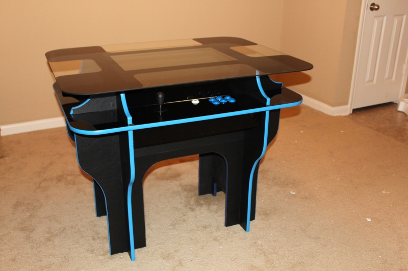
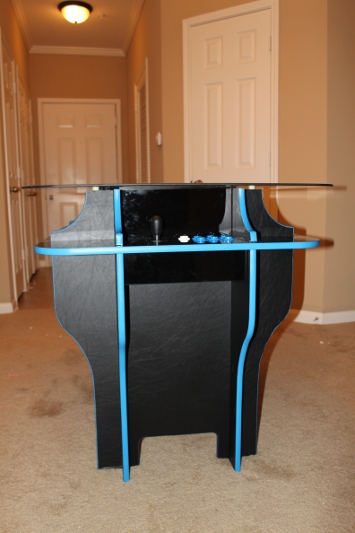
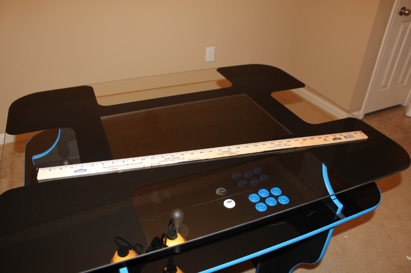
Cocktail Arcade Cabinet Build: Part 9 - The Computer Hardware and Software

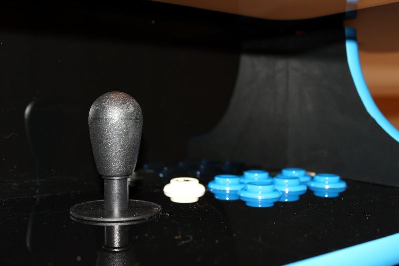
Wiring to one of the joysticks Power supply mounting plate Particle board drive cage with slots for seven 3.5 inch hard drives Motherboard on its mounting plate Mostly empty interior The IPAC-4 hiding under the monitor support The finished arcade cabinet with the top off

The Guts of the Table

The only new electronics I bought for the table were the I-PAC4, the buttons and joysticks, and the 24” LCD monitor. All the guts were transplanted from my home file server, whose job used to be playing movies on my DLP projector.

Arcade-Related Hardware

The computer hardware is mostly faster than it would need to be for an upright cabinet. It is an Athlon X2 3800+ with 1 GB of RAM and it has a 64MB NVIDIA 6200 LE PCIe video card.

NAS-Related Hardware

The motherboard also has 6 SATA ports, and I’m using every one of them. The arcade table is now the home of my file server. We built a little cage to hold seven 3.5” hard drives out of some of the left-over building materials. Six would have been enough, but the wood we cut ended up being long enough for seven, so that’s what we have.

The boot drive is an old 320 GB SATA disk I had lying around. It holds all the data needed to play games on the cabinet. Then there are five 1 TB disks in a RAID 6 array, giving me about 3 TB of usable space. The RAID drives are set up to spin down shortly after the cabinet boots up.

I’m very happy that I’m able to use my cocktail cabinet as my home file server. The table is fairly bulky but it has a ton of room for computer hardware on the inside.

How the Hardware is Mounted

We had a whole bunch of leftover melamine panel from my DIY white boards. We cut one panel each to mount the motherboard, power supply, and the hard drive cage to. We cut slots in the sides of some 6” x 2” inch pieces of our 5/8” particleboard and we glued/screwed those to sides of the interior of the table to use as rails.

The motherboard is attached to a melamine panel square with wood screws and some plastic spacers. The power supply is screwed and zip tied to a small panel. The original power supply we were going to use had four screw holes we could use; the power supply we ended up using only had two. The two screws are probably enough; the zip tie is really mostly there for my own piece of mind.

The melamine panels slide right down from the top into the rails. We glued/screwed small wood blocks onto the walls underneath the panels to use as bump stops so the components would drop right through to the floor.

There is a six-inch wide shelf in the center of the table that the monitor sits on. We didn’t end up having to measure that perfectly, we just used some rubber feet as spacers to push the shelf up just a bit so that the monitor is nearly pressed right up against the glass.

The Software

We’re running 32-bit Ubuntu 10.10 for the operating system. We’re using the Wah!Cade front end and SDLMAME and SDLMESS for all the emulated games.

Wah!Cade

I don’t have much to say about Wah!Cade. I didn’t try many other front ends, so I can’t really say if it is much better or worse than anything else. I’m happy with it so far. It looks fine and the config files are easy to work with.

In the future I would like a front end that would auto rotate the controls and display for me so that the controller that selects a game becomes player one. I can see this being pretty complicated to do properly, though. I have some games set to the forced faux cocktail mode and others are set to native cocktail mode. None of those settings will work very well if the game is rotated from portrait to landscape.

SDLMAME

SDLMAME is excellent. I wouldn’t have built a cocktail cabinet if it weren’t for the “new” cocktail video mode that splits the screen and shows a full display to player one and player two. This is a killer feature of SDLMAME and SDLMESS for me.

Every game I would ever want to play from up until at least the middle of the 1990s plays in cocktail mode without dropped frames at 720p on my hardware.

SDLMESS Saves the Day!

Using a computer LCD monitor almost ruined my cocktail cabinet. I was using Mednafen and Snes9x for NES and SNES emulation. I’m a big fan of Mednafen, and both emulators are wonderful pieces of software.

My plan was to use the player 3 position, which is one of the long sides, as the seat to play NES and SNES and other games. With the poor visibility from the bottom of the display, I was forced to rotate the video output using XRANDR. This really made my video card too slow to play and scale NES and SNES games. Mednafen and Snes9x don’t have facilities to rotate the game output.

SDLMESS can not only rotate the display, but it even supports SDLMAME’s cocktail mode! SDLMESS isn’t nearly as capable of an emulator as Mednafen or Snes9x, and it is very picky about which game images you feed it. When a game works, though, it works very well.

Once I finished shoe-horning SDLMESS into place it was pretty trivial to add TI 99/4a and Coleco Vision emulation to the cabinet. I’m very happy to know that my memory is correct. Munchman is a much better game than Pac-Man, and TI Invaders is far superior to the original Space Invaders! I also had the theme song from “The Attack!” stuck in my head for days…

I ended up wrapping all the emulators in little shell scripts that set the correct screen orientation and/or resolution. My front end is running rotated 180 degrees at 800x600 and SDLMAME and SDLMESS are running at normal orientation at 720p. I’m experimenting with running some native games; they tend to need to run with the screen rotated as well.

Cocktail Cabinets are More Expensive than Upright

Especially when they’re four-player… I wanted six buttons at each of the four control panels. I don’t think there are any four-player arcade games that use more than three buttons but I wanted the option to be able to play two-player six-button games in either portrait or landscape. Just about the only control interface that supports enough inputs for that is the I-PAC4, which costs more than twice as much as something like a GPWiz 40.

To run in the split-screen cocktail mode requires more CPU. Scaling the larger output of the split-screen cocktail mode requires more GPU. In general you’ll need more CPU and GPU horsepower to drive a cocktail cabinet.

DIY PVC Pipe Laptop Stand

With no laptop Side view with laptop Set up and cabled in its usual home

There really isn’t too much to say about this little project. We designed it and threw it together in about ten minutes, using leftover parts from my monitor stand and laptop rack builds.

Most of the construction is probably pretty obvious. The part we weren’t sure about was attaching the PVC J hooks to the piece of pipe at the top. We ended up cutting a notch in the pipe for each hook and we used the nails that came with the hooks to create sort of ad hoc hinges. It most certainly isn’t the best way to attach them but it was the best option we had on hand at the time, and it has worked surprisingly well.

The whole thing probably used just a few dollars’ worth of materials. It has been in service for a few months and it has been doing a good job of keeping the laptop monitor up in line with its second display. I should probably dye it black, but the white hooks match the white laptop quite nicely.

Cocktail Arcade Cabinet Build: Part 8 - Painting Plexi and Installing T-Molding

Blackened plexiglas with holes for buttons T-molding and plexiglas installed

The blackened plexiglas turned out really nice. We used a can of glossy spray paint to paint the back side of each piece. They come out with a very shiny black color and have a very mirror-like reflective quality to them. Please excuse these early pictures. The panels were all still very dusty in the work-shop.

We used the blackened Plexiglas for all the control panel surfaces, for the short vertical panels that cover up the control panel wiring, and also on the back wall of the control panel areas. We originally planned to cover the back walls of the control panels with vinyl. I’m glad we ran out of vinyl, because the reflective plexiglas looks REALLY nice back there. The reflections of the buttons in the back panel look quite awesome!

The plexiglas makes for a nice, smooth surface to rest your hands on but it is very hard to keep clean. Our panels are very mirror-like, so fingerprints stand out a bit more than if we were just using clear plexiglas to cover some artwork.

The Glass Tabletop

I don’t seem to have any pictures of the glass tabletop being painted, but there is a short video walking around the table before it was completely finished. In the video you can sort of see the poor viewing angle from the bottom side of the LCD panel that I described earlier. It gets much worse than that if you actually sit down on that side.

We ended up buying a 32”x42” piece of glass to use as the surface of the table. It is ¼” thick and has, I think, 4” radius corners. We were able to get this piece custom cut at a local glass shop for $55. We aren’t having any problems with the ¼ inch glass but I think it would probably be better to go with 3/8” or ½” instead.

We painted the underside of the glass just like the Plexiglas. First we taped off a rectangle to match the display area of our monitor as precisely as we could. Then we taped off the nicely rounded view ports over each control panel.

We sprayed a few coats of glossy black paint over the exposed glass, waited until the next day, and then peeled off the masking tape.

The glass sits on four little rubber bumpers with the painted side down. The paint comes off the glass pretty easily. We’ve removed and replaced the glass at least a half dozen times so far and the paint has peeled off a bit right at the rubber bumpers. After we touch it up we might try taping off a few square inches underneath with electrical tape. We figure that should keep the paint from peeling.

T-Molding

The T-Molding was really easy to work with. Most of it we were able to just muscle into place with our thumbs and palms. Some spots didn’t want to fit as easily, those we tapped in with a rubber mallet. Once it was in place, we trimmed the end smooth with a razor blade—it cuts quite easily.

There are 90-degree bends on both sides of each control panel. I’m not terribly happy with those sharp bends. We cut out a big V from the back of the molding so it would bend that far, but the bend is still a bit rounder than I would prefer. We also only have barely more than an inch of groove there for the end of the molding to grab on to. Two of them wouldn’t stick on their own so we had to glue them.

One of my favorite parts of the entire cabinet is the piece of t-molding around the control panels that wraps all the way around the table. It really ties the cabinet together.

The Ugly Unfinished Bits

I shouldn’t even be pointing this spot out. I doubt anyone would ever notice it in any pictures or videos of the completed cabinet. I sure notice them, though.

There’s a 5/8” gap in the plexiglas between each control panel. We could have worked a bit harder and got the plexiglas to touch there but there would still be a seam to cover. We aren’t entirely certain how we are going to cover it up.

One idea is to cover them up with tokens from meaningful arcades. We would need four of them, which might be difficult, and we’d still need to put something underneath them.

This article at blog.makezine.com got the gears turning in my head. I’m not so sure I would want to emboss anything, but I bet I could bend some aluminum into some sort of clip to slide around the two pieces of plexiglas.

I’m sure we’ll come up with something to cover that gap. It really hasn’t been a priority so far. We really just want to get the cabinet up and playing games!

Cocktail Arcade Cabinet Build: Part 7 - Applying the Vinyl

Close up of the sticky-back vinyl Another close up of the sticky-back vinyl A single piece of sticky-back vinyl installed

Applying the sticky-back vinyl covering to the cabinet was very simple but time consuming process. We spray-painted the cabinet around all the edges just in case the particleboard was visible anywhere between the vinyl and the t-molding.

All we had to do was clean the surface, peel off part of the backing, and press it down onto the surface. We slowly peeled off the backing as we were applying more and more of the vinyl from one end of the surface to the other while being careful not to create any bubbles or creases.

After each piece was glued into place, we had to trim around the edges with a razor blade. You have to make sure that the vinyl is flush with the edge of the board. If there is any overhanging vinyl, it will be very obvious once the t-molding is put in place.

How Does it Look?

It looks very good. At this point I think it was well worth the time, effort, and money to go with the vinyl. It looks right and it feels like it belongs in an arcade.

Poor Planning

I didn’t order quite enough vinyl… I’m pretty sure I forgot that we had to vinyl both sides of the board on the outsides of the cabinet. My poor planning actually forced us to improve the looks of the cabinet quite a bit. We decided to cover the back wall of each control panel with a piece of blackened plexiglas. The plexiglas looks much, much better back there than the vinyl would. It has a lot more depth back there now; you can see the reflection of the buttons and joystick on the back wall now.

Alternatives to Vinyl

I really like the way the cabinet looks with the vinyl and I am glad we used it. We’ve been trying to think up a good alternative. The vinyl is expensive, partly because of the high shipping costs. The vinyl alone was probably almost 20% of the cost of the entire cabinet. Applying the vinyl to the cabinet was a pretty time-consuming process. I’m pretty sure it took us more than two full evenings to finish. That’s probably over 6 hours.

The best alternative we’ve come up with so far is melamine board from Home Depot.

We used two 4’x8’ sheets of 5/8” particleboard to build the cabinet at a cost of about $17 per sheet. It took about $90 worth of vinyl, including the cost of shipping, to cover the cabinet. If we wanted a white cabinet we could have saved about $50 and 6 hours.

Melamine is a plastic. I recently used vinyl dye to color my LCD monitor stand and laptop rack, and I would expect vinyl dye to cover melamine just as fully and easily as it covers PVC pipe.

Vinyl dye costs about $6 per can. I’m pretty certain we could dye an entire melamine cocktail cabinet with less than two cans of spray paint, and I am absolutely certain it would take way less than 6 hours.

Cocktail Arcade Cabinet Build: Supplemental - a Mistake to Avoid When Choosing a Display

I still have two or three blog entries to write to bring us to the end of the cocktail cabinet build but in reality we are actually just a few cosmetic tweaks and a bit of assembly away from a completed cabinet. We were playing some games on it and we learned that we made a terrible mistake in our choice of monitor.

The LCD panel we used really does have awesome viewing angles, unless you try to look at it from the bottom side. This seems to be the case on the handful of computer LCD monitors that I tested. I’m guessing that they sacrifice viewing angle on the bottom to provide a better viewing angle from above. That way when someone stands behind you at your desk they will still see a nice crisp image on your screen.

I’ve tested the two LCD televisions we have here, and they seem to have similar viewing angles from above or below. I assume the manufacturers know that televisions are much more likely to be hung at or above eye level.

I’d like to find an LCD TV that has both the correct viewing angle and would fit well in the cocktail cabinet. The table ended up being just barely big enough to fit our 24” LCD monitor, and this monitor has a very small bezel on all four sides. In fact, the bottom bezel on my 21.5” monitors that I have on my desk would make them too tall to fit.

For now we’re just going to live with the fact that our four-player table is effectively a three player table. We were originally thinking about putting players 3 and 4 side by side on one side of the cabinet, but we thought it would be a little too cramped that way. If we stuck with that layout, we wouldn’t have a problem.

My plan is to rotate the display 180 degrees in the xorg.conf so that we can play 1-player widescreen games from the player 3 position.

This may hobble my cocktail cabinet but at least it will work. If would have been much worse if we tried to use this monitor in an upright cabinet.

Do It Yourself Dual LCD Monitor Stand

Monitor Stand From Amazon Monitor Stand From Amazon

Update: Replacing the do-it-yourself stand

I upgraded to a pair of 27” QNIX 2560x1440 LCD panels, and they were just too big for my custom stand. I wanted to build another one, but I just have too many fun projects going on right now, and I didn’t think I’d find time to do it.

I ended up buying an inexpensive, heavy-duty monitor stand instead. Most of the options that were available when I built my own monitor stand quite a bit more expensive than the stand I ended up buying for my QNIX monitors.

This time I was able to buy a heavy-duty, fully articulated dual monitor arm for about as much as I spent on parts to build the last one. There’s not much point in going the DIY route anymore!

The Back Story

I started running my first dual head desktop at home with a pair of 19” CRT monitors sometime around 1999-2000. In 2001 I “upgraded” to a pair of 14” LCD panels. Ever since that upgrade, for almost 10 years now, I have been wanting to buy or build some sort of dual monitor stand.

Completed stand on a nice, empty desk PVC with black vinyl dye PVC with black vinyl dye Flange bolted to the desk Monitor hanging on PVC J hook Pipe stand with PVC support Failed attempt to mount monitors on pipe flanges Failed attempt to mount monitors on pipe flanges

I ran those 14” panels for quite a few years. Probably for a lot longer than I should have. Sometime in 2005 or 2006 I ditched my separate desktop and laptop and started using a laptop as my primary workstation. The laptop didn’t have dual video outputs, so I traded my dual head for the convenience of having my primary computer with me no matter where I went. It was a very worthwhile trade-off; I plan to never have a separate laptop and desktop again.

Update: Never say never. I ended up building a new desktop computer in July of 2013!

When I upgraded earlier this year, one of my requirements was that the new laptop needed to support a pair of external displays. The laptop I chose has an HDMI and VGA port. This laptop can only drive two ports at the same time, so I can’t cheat and use the internal display as a third head.

I don’t really consider the current monitor stand to be a finished product. It is in its second iteration now and could definitely be improved upon. I am going to describe where we started, how we got to the point we are at now, and probably talk about some of the things I might do differently next time.

Some of the Design Goals

There were a handful of features we thought were necessary:

  • Adjust the angle of the monitors
  • Move the monitors left and right, so we could get them to meet up nicely at the center
  • The whole thing needed to be sturdy
  • Less expensive than a monitor stand we could order

The Early Ideas and Failure

The original idea was to build almost the whole thing out of steel pipe from Lowes.

The two “FAIL” pictures show everything we had in our original design. We used pipe flanges, which are ridiculously expensive compared to the rest of the parts, to bolt the whole rig to the desk. Then we put a pipe flange at the end of each arm. Then we bolted a small 1”x6” piece of lumber to the flange at the end of each arm.

At this point we needed a way to mount the monitors on the lumber. We ended up bending some metal strips into J-shaped brackets so we could literally hang the monitors on the lumber.

We did a horrible job fabricating those brackets. The idea isn’t terrible. It allows for rotating the angle of the monitors on two different axes, and it allows for moving the monitors left and right. There were a few things we didn’t like, though:

  • Our brackets were awful, they looked terrible, and we couldn’t manage to quite get the monitors to line up
  • The two extra flanges probably cost more than all the pipe we bought

PVC to the Rescue!

We weren’t sure PVC would work out but it ended up having quite a few advantages. We ended up buying a 10’ stick of the higher pressure-rated ¾” pipe for just a few dollars. The tee and elbow fittings are also only 20-30 cents or so each.

They also sell really handy hooks that fit each size of PVC pipe. We screwed a pair of ¾” PVC hooks to each monitor using the VESA mounting holes; we just had to drill the holes out a bit bigger to fit the M4 screws. I only ended up using the top screw for each hook. I ran out of long M4 screws. They have been hanging for over six months without any issue, so I’m not going to worry about it now.

Each monitor has its own PVC rectangle with tee fittings on both inside corners instead of elbows. The top tube on each PVC rectangle is slid over existing steel pipe (where the upper flanges used to be). Then we connected the bottoms of the rectangles to each other with various PVC fittings and very short lengths of pipe.

The bottom of the rectangle is “connected” back to the vertical steel pipe with a short section of PVC pipe. It isn’t really connected; it just rests up against it to keep the bottom of the monitors from sagging. There is a pair of PVC screw caps in there so I can adjust the angle, but they weren’t at all necessary. If I did it again I would just put a single pipe in there without the fancy fittings.

Putting Some Lipstick on that Pig

I’ve been wanting to post pictures of this rig for months but it looked pretty bad in white. The problem was that to paint it I would have to take it down. If I took it down I wouldn’t have my monitor stand.

I finally took it all down this week to “paint” it. I bought a can of “vinyl dye” from the auto parts store. It worked very well, covers very easily, and looks infinitely better than the white PVC that announces what pressure it is rated for.

I didn’t paint any of the steel pipe. I like the way it looks just the way it is.

The Cost

I probably bought a total of about $60 or $70 worth of parts, but I’m pretty sure I really only used about $30 or $40 worth of them. The cost would go down a bit more if I used less steel.

I would prefer to use less steel. I’m not terribly happy with the way the steel joins up with the PVC. It works and looks alright. I just don’t like it.

What I Would Like to Do Differently

Right now the PVC is mostly a two-dimensional structure. I have some ideas for a sort of triangular PVC cage that would support the monitors both vertically and horizontally. Then that cage could just drop down over the top of a single steel pipe coming out of the desk.

What I have already does its job quite well. I wish I built something like this 10 years ago!

Tweak btrfs-snap for More Frequent Snapshots

I have been using the btrfs-snap script for a few weeks and it is working very well except for one small problem. Btrfs seems to have trouble if you remove snapshots too quickly.

I made a few simple tweaks to btrfs-snap to help alleviate this problem. I added a check to make sure only one instance of the btrfs-snap script can be actively removing snapshots at a time. I also added a delay between snapshot removals.

This version of the script has been running on my laptop for the last few days, keeping a dozen snapshots at five-minute intervals without any problems. With the original script, btrfs-snap processes would start getting gummed up within the first few hours.

Update 2010-11-14:

I’ve been running this script for a little over two weeks now and I ran into my first runaway snapshot situation last night. Snapshot removal was hanging, and by the time I noticed it I had over 500 extra snapshots of each volume for a total of something over 1650 total snapshots on the file system.

After a reboot, snapshots could be removed again. Early on, the removals took over 30 seconds each, and disk I/O slowed to an absolute crawl. I don’t really want to be stuck with this many snapshots again…

I added a check to the btrfs-snap to make it skip snapshot creation if too many snapshots with the same prefix already exist.

Update 2010-11-29:

I seem to be getting gummed up more often lately, probably every few days. The file system isn’t getting clogged up with huge amounts of extra snapshots anymore, but by the time I notice things went wrong, my process table usually has a few thousand btrfs-snap processes sitting around.

They’re getting hung up trying to count snapshots. It seems that it isn’t possible to get an ls of the .snapshot directory while btrfs is in the middle of failing to remove a snapshot. I moved the check for the sentinel file up a bit so that it creates the lock before counting snapshots. I also added a little countdown loop so that it will give up if it can’t get the lock after a few tries.

Cocktail Arcade Cabinet Build: Part 6 - Fitting the Joysticks

We were thinking that routing the holes for the joysticks was going to be one of the hardest steps. It actually ended up being easier and faster than we ever expected.

We are using HAPP Competition Arcade Joystick. It looks like there are two common ways to mount these joysticks.

You can use a metal plate as your control panel and bolt them straight to it. We didn’t like this because we don’t want to see the bolts.

You can also use a thin wood control panel and screw it in from underneath. The joystick comes with a longer plastic spacer to help make up for the thickness of the wood. We wanted the joystick to be as tall as possible, and we didn’t think this seemed very sturdy.

How Did We Do it?

We routed a 2 9/16” square hole through our 5/8” thick particleboard control panels. Then we set the depth on the router so we could countersink the top lip on the joystick so it would be flush with top the of the particleboard. We got a nice snug fit on all four joysticks. Once they are pushed in, they are pretty tough to get back out. I am very happy with the results, since they might not even have to be screwed in.

Drilling the Hole in the Plexiglas

The hole for the joystick doesn’t have to be very big. The first hole we drilled, we used a 7/8” spade bit. We didn’t quite find center, and the joystick was rubbing in one direction. It was easy enough to clean that up, but we learned that it was better to just us a 1” bit instead. As long as the hole is completely covered by the joystick’s little plastic disk, it will be just fine.

What’s the Next Step?

Things are winding down fast now. Most of what we have left is just painting and decorating before we get to the wiring. The next step will likely be painting and applying the textured vinyl.

Countersunk hole for the joysticks Joystick sitting flush in the countersunk hole Joystick under unpainted plexigas Joystick with cover disc under plexiglas All the holes are cut and drilled Close up of a control panel with all its holes Test cut showing an accidental, questionable design

Tire Punctured by 5/8 Inch Wrench

It seems to have gone straight in How can this happen? It sounded like a machine gun as the wheel spun around

We were getting ready to start working on the arcade cabinet last when we realized that we didn’t have any of our bar clamps. John remembered that he lent them to our friend Joe the other day, so we took a walk over to Joe’s house.

When we got there he asked us if we had a few minutes because he wanted to show us what happened to him earlier. When we walked over to the car we noticed the small donut spare on the passenger side rear corner of the car. First he showed us some of the damage. The bumper cover had a split in it near the wheel well and every bit of plastic covering around the inside of the wheel well was torn up.

At first I was trying to figure out what sort of oddly shaped high curb he must have hit to manage to make that happen… Then he pulled the tire out of the trunk using the 5/8” wrench protruding from the tire as a handle!

We’re all very curious how it actually happened. We know he was driving at about 35 miles per hour on a straight stretch of road. I’m thinking the front tire may have driven over it and bounced it off the ground and that put it at the right angle that it could somehow puncture the tire. John thinks it may have somehow gotten kicked up over the tire and gotten wedged between the tire and the frame of the car then got forced in as the wheel turned.

Wrenches through tires seem to be a pretty rare occurrence. I only found one similar picture in a few quick Google image searches.

Cocktail Arcade Cabinet Build: Part 5 - Slots for the T-Molding

Cutting the slots for the t-molding went quite well. We just had to make a few test cuts with our slot cutting bit in a scrap piece of board to get the slot centered and then we were able to cut the slots on all the legs and arches very quickly.

The slotting for the control panels was a little more complicated and I have been worry about it a bit for the last few weeks. The problem we have is that the t-molding covers 5/8” and we need the molding to cover the 5/8” particleboard in addition to the 0.080” thick piece of plexiglas.

First we moved the slot for the control panels up 0.080”. The t-molding covers the plexigas perfectly at this height. Unfortunately, that leaves us with a 0.080” thick piece of visible particleboard below the t-molding…

We lowered our slot cutter to the very bottom of the wood and shaved off 0.080 inches creating a very thin notch. This is the cut that I have been worried about for a while. Surprisingly, we got a nice clean cut and the remaining particleboard on both sides of the slot seems more than sturdy enough to do its job.

Stack of slotted boards Test t-molding is flush with the plexiglas Test t-molding next to small test piece of blackened plexiglas Diagram of the plexiglas, t-molding, and the two slot cuts we had to make