Immediately after installing my monitor stand, it was obvious that I needed a good way to hide the cables that were routed out the back. Most people that use these stands wouldn’t see the cables, because they’re sitting directly in front of the stand. I am sitting at an L-shaped corner desk, so I am seated in such a way that I can see around the back.
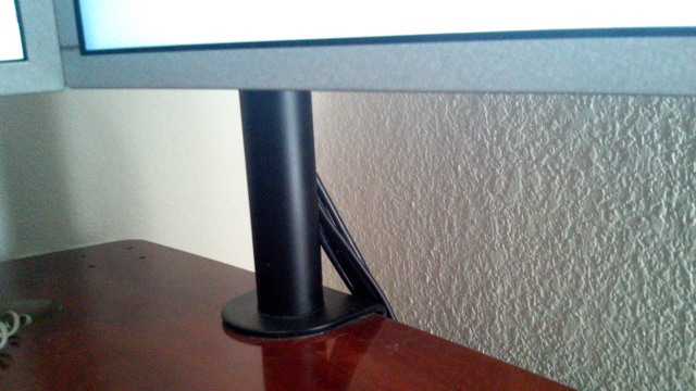
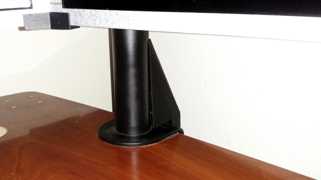
This seemed like a perfect job for my 3D printer, so I fired up OpenSCAD, and I got to work designing something that would hide these pesky cables.
I had some problems tuning in the final version
I started designing this object back in November—nearly six months ago. I had the first test print finished in December, and it came out surprisingly well. That original test piece is currently attached to my friend Brian’s monitor stand, and it is working well enough. I wanted to improve on that design, though.
I ran into some trouble, because I left town for almost six weeks. By the time I returned home, none of this was fresh in my memory. I didn’t remember the precise changes that I wanted to make, and being away from the code for so long made it harder to spot a major mistake.
I had accidentally used the poleDiameter variable where I should have used the baseToBack variable. These two variables represent two very real world dimensions, but they were close enough that they didn’t throw the printed part too far out of whack.
I changed the baseToBack value at least three times before realizing that it wasn’t having the intended effect. Remember to always pay close attention to the variables you’re using!
You can download the OpenSCAD source code for this part at GitHub.
- oknowton/3D-Printer-Models at GitHub
- Cable Cover for Monitor Stand.scad at GitHub
Designing to integrate with a real world object
Creating a 3D printed part that snaps into an existing, real-world part can sometimes be quite an easy task. All you have to do is create a model of important parts of the exiting object, and use your modeling tools to remove the difference of the real object from your new 3D printed part.
In the case of the monitor stand, this was mostly very simple, since it is simply an easily measured cylinder perpendicular to a flat, square bracket.
There was one aspect of my design that involved some guesswork. I wanted to 3D print some teeth that would grab on to the inside of the opening where the cables flow out. Measuring the width of the opening was easy. Guessing how much wider I needed to make the teeth for a reasonable friction fit seemed harder. Too tight, and the clips would break off. Too loose, and the cover wouldn’t stay in place.
Variables used in the examples
There’s a whole slew of variables defined at the beginning of the full OpenSCAD source code of this object. I’ve left those variables out of the example code snippets, but you’ll need to add those variable definitions to your OpenSCAD source file if you want to follow along.
1 2 3 4 5 6 7 8 9 10 11 12 13 14 15 16 17 18 19 20 | |
If you paste this code into the top of your OpenSCAD source, then you should be able to paste in any of my example code snippets and see exactly what I do.
Step 1: I had to start somewhere

1 2 3 | |
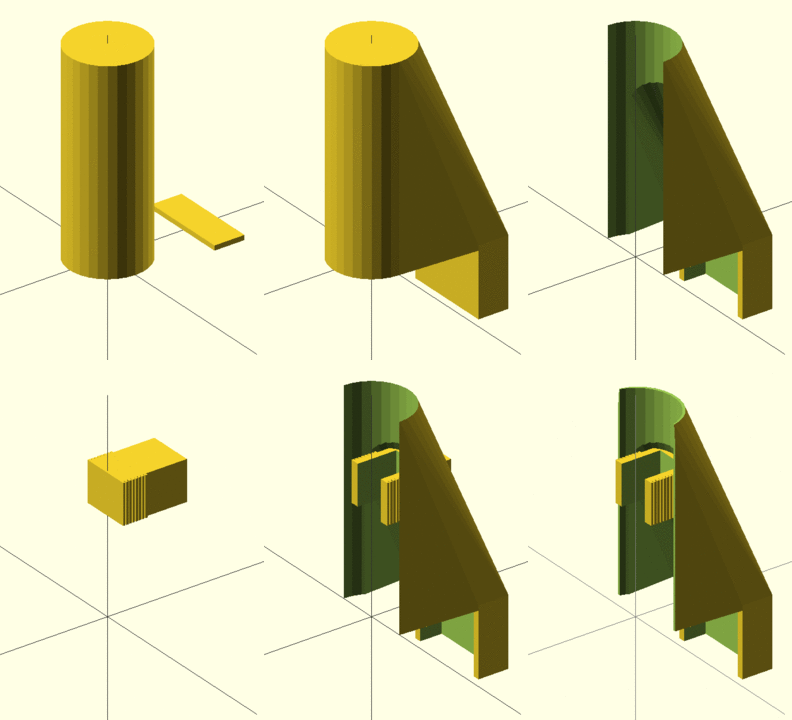
I wanted to create a smooth shape that would start above the wire opening, and stretch down to the back of the stand, and cover the wires until they were hiding neatly behind the desk.
I created a cylinder to match the vertical part of the stand, and I placed a small rectangular box to represent the base at the rear of my new cable cover. These were the starting points needed to be connected together.
Step 2: Creating a hull

1 2 3 4 5 | |
I’m not sure what a hull actually is in the mathematical sense, but I can tell you what it seems to be in a practical sense. It is somewhat like throwing a sheet over a set of 3D objects, and then pulling that sheet tight.
Using the hull function wrapped a skin around our two placeholder objects.
Step 3: Extending below the desk

1 2 3 4 5 6 7 8 9 | |
This is a pretty simple step. I need the cover to hide the cables as they go below the surface of the desk. All we need to do is add one of OpenSCAD’s “cube” shapes below the back of the object. That will give the cables somewhere to hide until they drop out of sight.
Step 4: Making room for the pole

1 2 3 4 5 6 7 8 9 10 11 12 13 14 15 16 17 18 19 | |
We have everything needed to hide the power and video cables that are coming out of the stand by the end of step 3, but it is just a big, solid object. There’s no room for the monitor stand or cables. We’ll use the OpenSCAD difference function to carve the monitor stand’s cylinder shape right out of our solid object.
Step 5: Hollowing it out

1 2 3 4 5 6 7 8 | |
Now we need to make room for the cables. This is the first time that I’d needed to hollow out the inside of a complex shape. I decided that the easiest way to accomplish this would be to scale down a copy of the solid cover object, and then subtract the smaller object from the larger object.
Deciding how much to scale the object down takes a bit of guesswork and tinkering. I think I did a reasonable job. The finished part is thick enough to be quite sturdy, but still thin enough that I didn’t waste too much time and material on the print.
Step 6: Creating the snap fitting

1 2 | |
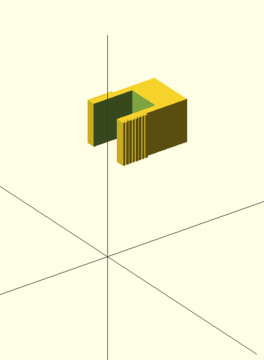
This is the part of the project that I am the most excited about. We need a way to hold the cover in place. My idea was to create a ribbed bracket that would snap into place in the oval-shaped opening on the back of the monitor stand. The hope being that the ribs would hold the part in place.
To get started, we just need to create a cube shape and move it in the correct location with the translate function.
Choosing a size for the cube and a height for the ridges was a bit of a guessing game. Measuring the width of the hole with a caliper was easy. Figuring out how much bigger the “arms” needed to be in order to apply enough grip was guesswork.
Step 7: Adding the ridges
1 2 3 4 5 6 7 8 9 10 | |
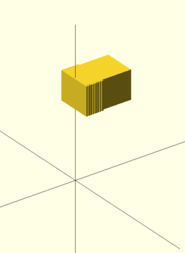
The ridges are just a series of flat “cubes” that are even so slightly wider than the central cube. We can use an OpenSCAD for loop to place a number of equally spaced ridge cubes.
Step 8: Making the snap fitting more flexible
1 2 3 4 5 6 7 8 9 10 11 12 13 14 15 16 17 18 19 20 | |
That solid cube with the ridges on the sides would probably be too rigid to fit into the monitor stand. I figured that we could carve out the center, leaving behind a pair of slightly flexible arms. How thick do those arms need to be? I have absolutely no idea. I just took a guess, and it worked well enough. They’re flexible enough that I can still remove the cover, but it is quite an effort to get it to come off. I haven’t broken the arms in my removal attempts, so I guess I didn’t choose too poorly!
Step 9: Putting the pieces together
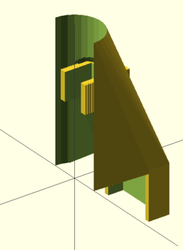
1 2 3 4 | |
Now we can bring the hollowed-out cover back and join it to our new snap piece. They fit together pretty well, except for that little piece of the snap cube sticking out the back.
Step 10: Trimming the excess from the snap fitting
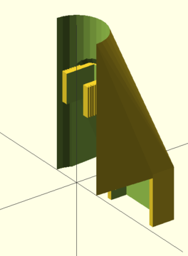
1 2 3 4 5 6 7 8 9 10 11 | |
There is probably a better way to remove the extraneous piece of the snap that is sticking out of the back, but we’re going to use the simple, brute-force method. We’ll just repeatedly subtract the hollowCover from the snapDoober while moving the cover backwards a couple mm each time.
At this point, we have a workable cover to hide those pesky cables. There are still some minor adjustments that we can make to improve our 3D print.
Step 11: Cleaning up the edges
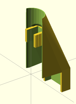
1 2 3 4 5 6 7 8 9 10 11 12 13 14 15 16 17 18 19 20 21 22 23 24 25 26 27 28 29 | |
This may be due to my printer not being calibrated perfectly, but I was unhappy with my first test print. The edges where the cover meets the vertical pole of the monitor stand come to a very narrow point. I wasn’t very pleased with how that edge looked, so I added some code to shave a few mm off that front of the cover. That turns those points into a slightly squared-off edge.
Test fitting the print
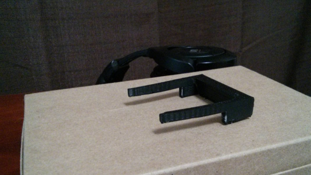
1 2 3 4 5 6 7 8 9 10 11 12 13 | |
Printing the entire cover just to test it out would be wasteful. It would eat up a whole lot of plastic, and the entire print job takes something like five hours to run. Instead, I wrote some OpenSCAD code to carve a slice right out of the middle.
The final print
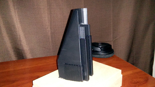
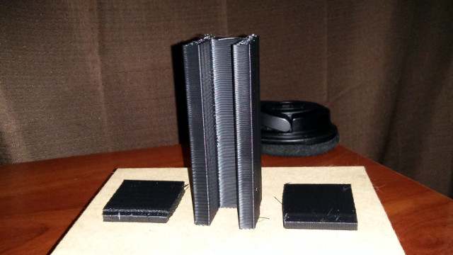
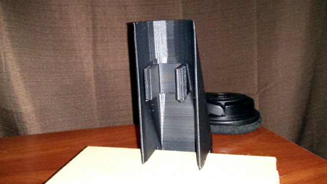
I’m very pleased with how the cover came out. It isn’t perfect, and there were a couple of failed prints, but it is doing a great job of tidying up my desk. In retrospect, I’m not certain why I decided that the part that drops down behind the desk had to be a cube. It would have looked much nicer if I made the hull using half of a cylinder in the back instead.
I didn’t realize this until I was already printing test pieces, and I didn’t want to go back and risk goofing up a measurement. The cover is still doing its job splendidly, and I learned a lot about OpenSCAD in the process.
- Mount-It! Articulating Monitor Arm at Amazon
- Cable Cover for Mount-It Monitor Stand at GitHub
- Cable Cover for Mount-It Monitor Stand at Thingiverse
What’s next?
You can probably see the gaping hole in my desk where the grommet is supposed to go. I used to have a hacked together grommet with AC power outlets and USB ports. I had to move it out of the way when my monitor stand arrived, and I was temporarily using that hole as a better location for the stand. I’ve since moved the monitor stand, but I haven’t put the grommet back. It is just too ugly.
I’d like to print a replacement, but I haven’t decided exactly what ports and adapters I’d like to fit in there. A couple of AC outlets are a must. They come in handy when I need to plug in a soldering iron, or I need to work on a random laptop. Speaking of laptops, an RJ-45 jack connected to my switch would be very handy as well.
The USB ports will need to be upgraded to USB 3, and I’ll want at least one 2 amp USB charging port. I’m definitely open to suggestions as to which other kinds of ports I should attempt to squeeze into this new grommet!