Gift Ideas For Geeks - 2015 Edition

| Comments

It has been almost a year since I wrote my last “gift ideas” post, and Christmas is almost upon us once again. During this time of year, you might be looking to find a gift for a family member, friend, or a coworker. I’m not usually very good at coming up with ideas for gifts, so I’m compiling a short list of things a person in my own demographic would enjoy receiving.

Some fun and useful items from previous years’ lists are making an appearance again, along with some new items. I’ve done my best to keep this list as general as possible. I don’t want you to have to worry about whether the recipient has an Xbox One or Playstation 4, or an Android phone or an iPhone.

I own and regularly use almost every single thing on this list. There are a few items that are no longer available, so I listed a comparable item in those cases.

Rechargeable USB Battery Pack ($7 and up)

Rechargeable battery packs have always been at the top of this list, but they are starting to become far more ubiquitous and much less geeky. I thought I was going to drop them from the list this year, but I still keep finding people that don’t have one of these ridiculously useful items.

Swift Gear 2600mAh battery pack charging my Nexus 7

USB battery packs come in all sorts of different sizes and capacities, and they come in handy all the time. My first battery pack was a small lipstick-sized charger with a flashlight, very much like this PowerBot 3000 mAh battery charger at Amazon.

My small 3000mAh battery pack is light enough that I don’t notice it is in my pocket, and it has enough juice to restore about 60% of my phone’s charge. That little guy has been more than enough to get me through several long airport layovers. The flashlight is a handy little bonus, too!

We also have a giant 20,000 mAh battery pack from Kmashi. That giant Kmashi can charge two devices at once, and it can fill up my tablet and phone more than once without needing a recharge. However, I can’t recommend the 20,000 mAh model—it is just too big and heavy. Kmashi also has 10,000 and 15,000 mAh models. The 10,000 mAh model only weighs about half as much as the 20,000 mAh model, but it still has more capacity than most people would ever need.

Arduino Starter Kit ($55 to $130)

The Arduino is a nifty little hardware prototyping platform, and it is a great way to dip your toe into the world of hardware development. An Arduino board all by itself isn’t very useful. When my first Arduino board arrived, the first thing I did was program it to blink an SOS on its built-in LED.

This isn’t very exciting at all. You need other electronic components if you want to do something interesting. You need parts like LEDs, resistors, buttons, motors, and buzzers. The easiest way to get going is to buy an Arduino starter kit.

I pieced together my own starter kit, but that wouldn’t make a very good gift. The Official Arduino Starter Kit and the Sparkfun Inventor’s Kit are both good choices, and they both come with a similar array of parts. The official kit seems to come with a larger printed guide, while the kit from Sparkfun comes with a nice storage case.

Of the two, I think Sparkfun’s Inventor’s Kit is a better gift and a better value. Sparkfun’s carrying case is a nice touch, and their holder for the Arduino and breadboard looks pretty convenient.

If you’d like to save money, you can go with a more generic kit. This Arduino Uno Ultimate Starter Kit is about half the price of the other two kits. It may have fewer components than the other two kits, but it definitely provides a better “bang for the buck.”

The Swiss Army CyberTool 34 ($80)

My Swiss Army CyberTool is easily the most useful tool I’ve ever owned. This tool was given to me as a gift sometime near the end of the last millenium, and I’ve probably used or misused my CyberTool at least once every month since then.

The CyberTool has all the tools you’d expect to find on a Swiss Army Knife, like knives, scissors, and a corkscrew. It also has additional geeky tools that I find invaluable. The CyberTool has an excellent bit driver with four double-sided bits, and they’re exactly the bits you’re likely to need when working on a computer. In fact, the bit driver is exactly the right size for tightening brass motherboard stand-offs.

Victorinox Swiss Army CyberTool 34

I use my CyberTool 34 along with my 3D printer quite a bit these days. The precision scissors easily remove adhesion pads from the corners of prints, and the awl comes in handy when a hole in the print comes out a bit too small for a screw. I can quickly and carefully make those holes just big enough for the screw to fit.

Many people seem to prefer Leatherman-style multitools—tools based around a full-sized pair of pliers. These are very useful tools, and I carry a Gerber multitool in my laptop bag. I just don’t have a lot of use for a big pair of pliers. If you’re buying a gift for someone like myself that is always taking apart computers or working on electronics projects, then the Victorinox CyberTool 34 is definitely the better choice.

A 3D Printer ($500 to $1200)

There are hundreds of great-looking 3D printers and 3D printer kits available these days, but I’m only going to talk about two printers here. Aside from the two printers I’m going to talk about, there are quite a few kits in the $300 range. A friend of mine bought one of the printers, and while these printers are a viable option, I don’t think these cheap 3D printers would make a very good gift.

My MakerFarm Prusa i3

If you are buying a 3D printer for someone that likes to tinker and build things, then you can’t go wrong with a Prusa i3 printer from MakerFarm. I have had my MakerFarm 8” Prusa i3 3D printer for more than a year now, and it is one of the best things I ever bought. If I were buying another 3D printer today, it would most definitely be the 12” MakerFarm Prusa i3. The MakerFarm printers are well made, and their wood frame is quite rigid. MakerFarm has an 8” model for about $500, a 10” model for around $600, and a their 12” model is closer to $700.

I do realize that a kit might not make the best gift, but I would tend to recommend going that route anyway. Assembling a 3D printer is a great learning experience, and it is useful to understand just what your printer is doing as it is moving around.

If you don’t want to go with a kit, I’d have to recommend the FlashForge Creator Pro. It is a Makerbot Replicator clone that arrives fully assembled and ready to print. The FlashForge Creator’s build volume is comparable to the 8” MakerFarm kit, but the FlashForge Creator costs about twice as much at around $1,200.

We just ordered a FlashForge Creator Pro at TheLab.ms makerspace, and I got it up and running a few days ago. Even with a crowd of people looking over my shoulder the entire time, I had the machine assembled and printing in less than thirty minutes, and I’m impressed with the quality right out of the box.

The FlashForge Creator Pro arrives almost completely assembled. I just had to use two screws to attach the print head, snaps some filament guides in place, and it was ready to print. I was worried when we opened the box, but most of the fasteners were for assembling the acrylic door and lid.

Bodum Double Wall Mugs ($27)

I use my double wall cups from Bodum every single day. They not only look great, but they’re also extremely functional. I use my espresso machine to make an awful lot of lattes, and espresso is a pretty fragile thing. If you pour your tiny shot of espresso into a cold ceramic mug, you will almost immediately bring it down to room temperature and ruin the flavor.

That means I have to warm up my mug first. The double wall cups from Bodum are not only insulated, but the inner layer of glass has very little thermal mass. That means I don’t have to warm up my mugs, and I can start drinking sooner.

My laboratory beaker mug made the list two years ago, and it is probably made out of the same sort of glass as the Bodum cups. The biggest difference would be the lack of a second layer of glass. I used my beaker mug for several years, and I cleaned it in the dishwasher once or twice a week. A few months ago, I found it broken in the dishwasher. To be honest, I didn’t think the dishwasher was the best way to wash the beaker mug, but it did weather the storm of the dishwasher better that I had anticipated!

The beaker is definitely the geekier of the two options, but I still prefer the Bodum cups. They’re just more practical. I prefer the 12-oz size Bodum glasses without handles, but they come in an assortment of different sizes and shapes. They even have them in the right size and shape to keep your beer cold and your hand warm!

A Coffee Subscription ($9 to $25 per month)

Plenty of the geeks I know drink a lot of coffee, including myself. If you know someone that is drinking terrible coffee from the supermarket or even from Starbucks, a coffee subscription is an easy and inexpensive way to upgrade their coffee-drinking experience.

I’ve been enjoying my subscription to Craft Coffee for nearly two years now. My first shipment from Craft Coffee included an Ethiopian Yirgachiffe from Slate Coffee Roasters. The notes on the bag read, “Light, pillowy and clean, with flavors of dried strawberries, confectioner’s sugar, and breakfast cereal.” I thought this sounded like a bunch of hogwash, but boy was I wrong! It really did smell and taste like breakfast cereal—like Frankenberry cereal.

If you do place an order with Craft Coffee, you can use my referral code “pat1245” when you place your order. You’ll receive a 15% discount, and they’ll give me a free month of coffee. People have been using my referral code more often than I would expect, and no one has come back here to complain. I’m assuming that means they also feel that Craft Coffee is an excellent value.

Angel's Cup Shipment

I was lucky enough to be shipped a Black Box from Angels’ Cup last month, and every sample in the box was amazing. The first bag we opened was a delicious natural process Ethiopian coffee. I always enjoy Ethiopian Yirgacheffe beans, and this was without a doubt the best Yirgacheffe I’ve had all year. One of the samples was aged in bourbon barrels before roasting, and it was the most unique coffee I’ve ever brewed.

The only label on each bag of Angels’ Cup coffee is a number and a roasting date, and they have a smartphone app. You punch in the number on the bag, and you tell it what you think of the beans. You tell it how dark they are, what they smell like, and what sort of flavors you can pick out. The app tells you how accurate you were and tells you more about the coffee.

It was fun, and my wife enjoyed figuring out what was in each bag. She was very excited when she was correct about that first bag of Ethiopian Yirgacheffe coffee.

You can use the coupon code “patshead25” at Angels’ Cup, and you’ll save 25% on your first delivery in a new subscription. Unfortunately, this coupon code does not currently work on gifts.

Beginning My Home Automation Journey With The ESP8266 And The ESP210

| Comments

I’ve been contemplating the idea of implementing some home automation for a very long time. The benefits just hadn’t been exciting enough to encourage me to get started. Turning lights on and off didn’t seem all that interesting to me.

A number of small things came together recently that gave me just enough encouragement to start implementing some automation. Every day when I wake up, I make a delicious latte for myself using my Rancilio Silva. It is an excellent machine, but it takes 20 or 30 minutes to get warmed up enough to pull a good shot of espresso.

My home office is upstairs, and my espresso machine is downstairs. I often forget to run downstairs before heading to the office. When I do forget, that means I walk downstairs to a cold espresso machine, and I have to wait at least 20 minutes for my coffee.

Radio Controller Power Outlets

There happened to be a sale on Etekcity RF-controlled power outlets at Amazon one day. I found an article on hackaday.io explaining how to control these AC outlets using an Arduino. I had already been messing around with ESP-01 WiFi dev boards for a while, and I knew how easy it was to load Arduino sketches on them.
Three Etekcity Remote-Control Power Outlets

I immediately ordered a 3-pack of Etekcity remote-controlled power outlets. Building a little WiFi to 433 MHz RF bridge seemed like a good idea, and the 3-pack of Etekcity outlets was about half the price of a single Belkin WeMo outlet. How could I beat that?

Reading the RF codes with an Arduino

I found a write-up over at Hackaday.io about controlling these Etekcity power outlets using an Arduino. He is using the RCSwitch Arduino library to communicate with his Etekcity power outlets, and it turns out the RCSwitch library is very simple to use.

RCSwitch ships with an example sketch named ReceiveDemo_Advanced. All you have to do is wire up an inexpensive RF 433 MHz receiver to your Arduino, and upload this sketch. Then you just start hitting buttons on your Etekcity remote control, and the remote control codes will be printed on the Arduino’s serial port.

I completed this part of the project before any of my ESP8266 boards arrived. I just plugged an RF receiver into on of my Arduino boards, hit all the buttons on my Etekcity remote control, and made a note of the codes.

Transmitting the RF codes with an Arduino

Testing the codes and RF transmitter was even easier than reading the codes from the remote. The RCSwitch library also comes with a sketch named SendDemo. I just added codes corresponding to my own Etekcity power outlets to the demo.

I wired the RF transmitter to the Arduino and uploaded the sketch, and I plugged my IKEA floor lamp into one of the Etekcity outlets. When the Arduino booted back up, the power outlet began turning on and back off once every couple seconds.

This was pretty exciting for me. That lamp was the biggest real-world device I’ve ever controlled with an Arduino!

The Node.IT ESP210 is awesome

I started this project with an ESP-12 on a cheap breakout board adapter. The ESP-12 boards work great, and they are ridiculously inexpensive. Unfortunately, they’re a real pain in the neck during development. I hate having to connect four or five wires to my USB FTDI every time I need to upload new code. Those big, cheap breakout boards for the ESP-12 are kind of a nuisance, too. They’re just too wide to be used conveniently with a breadboard!

Prototype ESP210 RF433 Web Server

The fine folks at Electronic Sweet Peas were kind enough to send me a couple of preproduction models of their wonderful little ESP210 boards. The ESP210 is an ESP8266-based dev board with an integrated USB to serial chip and a voltage regulator. I don’t know how they did it, but they managed to squeeze those two major upgrades and all the pins of an ESP-12 onto a board nearly as tiny as the ESP-01!

It was a piece of cake to pull the ESP-12 out of my prototype and swap in the ESP210 in its place. I was able to upload the code without making any changes, and it worked perfectly!

The ESP210 isn’t just another ESP8266 development board. It is part of the Node.IT family of tiny, modular add-on boards called “+One” modules that plug into the ESP210 board. There are +One modules that offer things like a real-time clock, additional analog or digital GPIO pins, and even humidity sensors or Micro SD card slots.

How far did this get me?

Pretty far! It was simple enough to control the outlets from the command line using curl, or with browser bookmarks on my phone. Before long, I had the lamp in my office turning off every time Steam launched a game. I was also able to use Tasker on my Android phone to turn on my espresso machine as soon as I unplugged my phone in the morning.

This was a good start, and it gave me some idea of how useful home automation can be. Unfortunately, controlling multiple switches from multiple computers won’t scale very well.

Controlling the ESP8266 to RF bridge with OpenHAB

I’ve since set up an OpenHAB server that lives on my power-efficient virtual machine server. It is doing a great job of controlling my devices and keeping track of what I’m doing.

Creating OpenHAB rules for my Etekcity power outlets was easy. OpenHAB has a sendHttpGetRequest function. I just have to call that function with the correct URL whenever a switch is toggled.

1
2
3
4
5
6
7
8
9
10
11
12
13
rule "Turn Office Lamp off"
when
  Item Light_SF_Office_Lamp changed to OFF
then
  sendHttpGetRequest("http://esp8266/switch/5576140")
end

rule "Turn Office Lamp on"
when 
  Item Light_SF_Office_Lamp changed to ON
then
  sendHttpGetRequest("http://esp8266/switch/5576131")
end

I could easily write several thousands words about the things I’ve done so far using OpenHAB. I’ll leave that for future blog posts.

You can find the code for my ESP8266 RF Bridge at Github!

I uploaded a copy of my ESP8266 Wi-Fi to RF433 bridge repository to GitHub. The README file really needs some attention, but other than that, it should be good to go. Just plug the data pin of your RF433 transmitter into GPIO 2, then replace the ssid and password variables with the correct values for your network, upload the sketch to an ESP8266, and you should be ready to go!

Building a Low-Power, High-Performance Server to Host Virtual Machines

| Comments

UPDATE: I used this hardware for two years. It was a fantastic build, and it performed exactly as I expected it to. The AMD 5350 and 5370 processors were fantastic little chips, but they’re not in production any longer. That makes them difficult to find, so they’re no longer a good value.

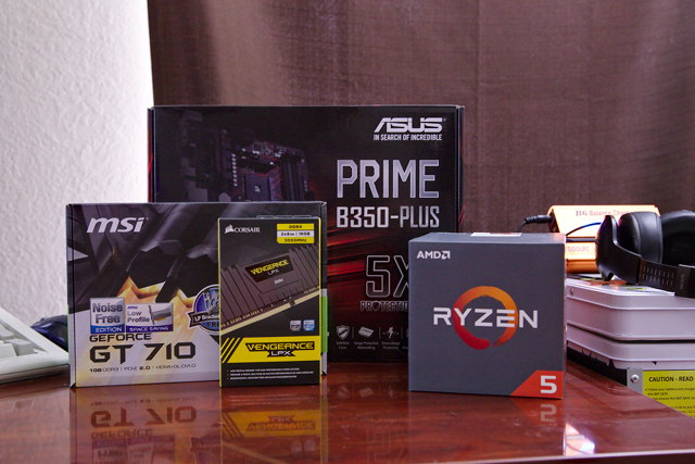
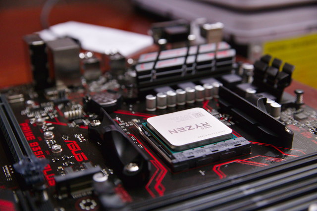
I’ve been looking for an excuse to use a Ryzen processor in something. An upgrade to my KVM homelab server seemed like a great idea. My power consumption has doubled, but it still seems reasonably low to me. Especially when you consider that my CPU performance increased by nearly six times!

I built that Ryzen homelab server so many years ago now. If you’re shopping today, you should check out Brian Moses’s Topton N5105 NAS motherboard. It is efficient, small, has plenty of SATA ports, a couple of NVMe slots, and even has four 2.5 gigabit Ethernet connections!

Back in the late nineties, I had two desks with three CRTs, two permanent desktop computers, and a laptop. My desk at the office didn’t look much different. At the time, you needed to have several computers around if you needed to run different operating systems, or even different versions of the same operating system.

Then VMware showed up, and I was hooked on the concept of virtualization immediately. It was the best thing since sliced bread. I no longer needed to keep several computers running at my desk. All I had to do was load one machine up with as much RAM as possible. That’s what I did, and that’s what I’ve been doing for the last 15 years or more.

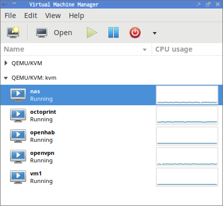
Virt-manager Machines

My needs have shifted quite a bit in that time, though. At some point, I replaced VMware with VirtualBox, and then I replaced VirtualBox with KVM. In recent years, I haven’t been booting up virtual machines as often as I used to. In the last few months, though, I’ve been running more software that needs to be highly available. Not in the “five nines” availability sense, mind you. I just don’t want things like my home automation to stop working while I reboot my desktop computer for a kernel upgrade or a gaming-related problem with the Nvidia driver.

My requirements

I wanted to build something energy efficient. My current needs don’t require much CPU at all, so I don’t need a 16-core, 32-thread monster homelab machine like my friend Brian, but I’d like to squeeze in as much CPU power as I can. I don’t need a lot of disk space, but I’ve been wanting to play around with Linux’s new dm-cache module, so I planned on buying more disk than I actually needed.

This new server currently only needs to be able to perform two important duties. It needs to be able to run my 3D printer, and it needs to be able to run my home automation software: openHAB. A single Raspberry Pi with an SD card could easily manage both these tasks, but I want to make sure I have enough horsepower for other tasks that I might want to offload from my desktop in the future.

tl;dr: My parts list

Total price: $746.59

Budget-friendly alternative parts list

Less memory, no solid-state drives.

Total price: $517.63

UPDATE: This blog post is getting old, and the parts I used are becoming harder to find. The AMD 5370 processor is a straight upgrade over my AMD 5350 processor. It is a little easier to find, but it is still getting pretty old. I’m going to have to revisit low-power KVM server build later this year.

Choosing a motherboard and CPU

My first plan was to use an Intel Celeron J1900 CPU. The motherboards with four SATA ports and an integrated J1900 cost about $80, they sip power, and they’d easily surpass my minumum requirements. It almost seemed like a no-brainer.

However, I am glad I did a little more research. I ended up buying an AMD 5350 processor and a matching motherboard. My research told me that the 5350 is 15 to 20 percent faster than the J1900, and it should only use 3 watts more at idle. Also, the Intel J1900 boards all used laptop DIMMs. The AMD 5350 motherboard and CPU ended up costing a few dollars more, but I probably saved that money when I was able to buy less expensive RAM.

The Motherboard and CPU

I prefer to use AMD processors whenever it makes sense. There are fewer situations where this makes sense every day, but this does happen to be one of them. Intel divides up their market by not offering certain features on different processors in their line-up. There have been plenty of times when newer, more expensive Intel processors are missing features that their older processors had. I’ve been bitten by this before when I replaced a Core Duo laptop with a Core 2 Duo, and the Core 2 Duo didn’t have VT extensions.

This isn’t something I’ve experienced with AMD processors. With AMD, I expect to find newer, better, faster processors to have all the features of the previous generation of processors.

Also, the AMD 5350 has a huge advantage over the J1900—the 5350 is nearly 20 times faster when it comes to AES encryption. Using all four cores, the Intel Celeron J1900 wouldn’t even be able to keep up with a single SSD. The AMD 5350 should have no trouble keeping pace with the full throughput of a pair of SSDs using only a single core. This is very important for me, because I intend to encrypt my disks.

All the comparable AMD and Intel motherboards I looked at top out at four SATA ports. It would be nice to have more, but I can always add a SATA PCIe expansion card.

How much RAM? As much as possible.

I learned two or three things very quickly when I started using VMware over 15 years ago. Unless you’re trying to crunch lots of numbers, CPU is probably not going to be your bottleneck when trying to shoehorn more virtual machines onto the same server. You’re going to run out of memory first.

Memtest86+ Running On The Power Efficient Server

That said, you can almost always shoehorn one more virtual machine onto a server. On more than one occasion in the early VMware days, I reduced the memory of all the virtual machines on my desktop by 10% or so just to make room for one more machine.

Memory is cheap and plentiful now, so there was no reason to not max out the memory in this little server. That’s only 16 GB—half as much as my desktop. It’s also much more than I expect this virtual machine host to ever need.

Choosing storage

The choice of storage hardware depends very heavily on the software being hosted inside your virtual machines. For my use cases, I don’t need a lot of storage. I could get away with using a pair of small solid-state drives in a mirror. They’d be nice and quiet, and would barely use any power.

However, I want to experiment with dm-cache. dm-cache allows you to use a fast storage device like an SSD as a read/write cache for slower devices. My hope is that dm-cache will allow the noisy, power-hungry spinning platter hard drives to spin down most of the time. I need both SSDs and conventional hard drives in order to test dm-cache.

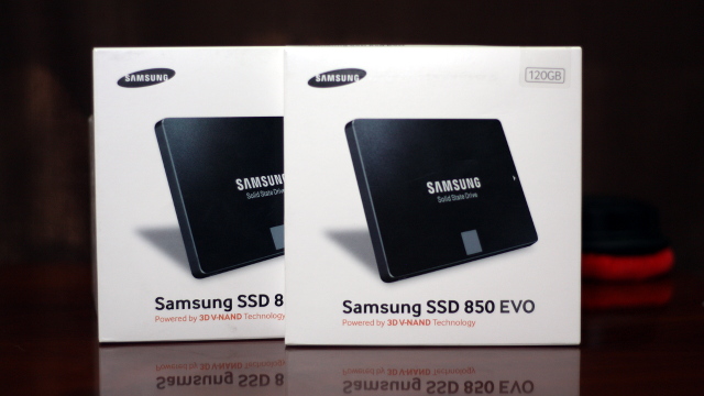
I chose to mirror a pair of Samsung 850 EVO SSDs to use as the boot device and dm-cache device. The Samsung EVO 840 drives have done extremely well in the SSD Endurance Experiment, so I thought Samsung’s newer models were worth trying. They’re fast, durable, and reasonably-priced. That’s a good combination.

I also bought a pair of 4 TB Toshiba 7200 RPM disks. I was planning to buy 5 TB Toshiba drives, because they are a better value, but they were on backorder when I was building this server. Backblaze seems to have nice things to say about the 4 and 5 TB Toshiba hard drives, and I’m still a little unhappy with Seagate. The Toshiba drives were also priced a little better than the other drives I liked.

I set up the drives using Linux’s software RAID 10 implementation. Most people don’t know that Linux lets you create a RAID 10 with only two drives. This is handy, because it makes it extremely easy to add drives to the RAID later on. Also, Linux’s RAID 10 implementation allows you to use odd numbers of drives in the array. That means I can add a third 4 TB drive later on for an extra 2 TB of usable space.

Even if dm-cache ends up being terrible, I’ll still end up with a versatile server. I can always store most of my virtual machines on the SSDs, and use the 4 TB drives as a NAS.

Choosing a case

This is usually the easy part. I’m pretty easy to please when it comes to cases. If it were still easy to find beige cases, I’d probably still be buying them today. Since I can’t do that, a simple black case is usually my preference.

Since I was already planning on using a mini-ITX motherboard, I started out focusing on small cases. The Cooler Master Elite 130 and Cooler Master Elite 110 were both at the top of my list. They’ve both small, reasonably priced cases with just enough room for all the components I was using. They’re also big enough to fit a standard ATX power supply, and that makes shopping a little easier.

This would have been a fine way to go, but I decided it would be best to have room to add more hard drives later. My friend Brian has used the SilverStone DS380B case in at least one of his do-it-yourself NAS builds. It is an awesome case, but I decided to be a cheapskate and use a simpler case. I ended up buying the Antec One.

All Part Installed In The Antec One ATX Case

I’m very pleased with the Antec One case. Much more pleased than I had expected. It has five 3.5” drive bays, so I can easily add three more drives. If that’s not enough, I can always 3D print some adapters to mount hard drives in the three 5.25” drive bays. I doubt it would ever come to that.

The tool-less 3.5” drive bays are mounted transversely, so you don’t have to worry about bumping into other components when removing or inserting drives. This was one of the features I always wished my desktop computer’s NZXT Source 210 case had.

The Antec One case also has a pair of 2.5” drive bays. The second 2.5” drive bay is my only complaint about this case. Instead of being a normal drive bay that you slide the drive into, it is instead a set of four screw holes on the floor of the case. I was able to connect the cables to the second SSD in that “bay,” but I don’t like the way the cables press on the floor of the case.

If you’re looking for a case with lots of drive bays, hot-swap drive bays, or just easier to access drive bays, check out my friend Brian’s list of his top three DIY NAS cases at Butter, What?!

Choosing a power supply

Generally speaking, larger power supplies tend to be less efficient when operating at a small percentage of their maximum capacity. There are also different levels of “80 Plus” certification that define how efficient a power supply is while operating at different percentages of its maximum load.

The difference between the lowest and highest “80 Plus” certifications is between 10 and 14 percent depending on load. The components in this build don’t consume much power, so I don’t think it is worth investing in a more efficient power supply. That extra 10 percent efficiency will only save about three watts. That’s only only 1 kWh every two weeks.

I ended up buying the Corsair CX430 power supply. It is a good value, reasonably quiet, and I could fill the Antec One case with hard drives and still have plenty of power to spare.

Notes on dm-cache

I made some poor choices in my initial setup in regards to dm-cache. Some dm-cache automation has been integrated into newer releases of the LVM toolset, but I’m running Ubuntu 14.04 LTS on my new server, and its LVM tools are too old for this. Also, it sounds like the LVM dm-cache automation requires that both the cached device and the cache reside in the same volume group. That isn’t how I wanted to set up my volumes.

I seemingly managed to get dm-cache configured, but it didn’t seem to be working correctly. I set up cache and metadata devices, and I created and mounted a dm-cache device. It worked in the sense that I was able to mount the new cached block device, and I was able to run benchmarks against it.

Unfortunately, it never generated any reads or writes on the SSD. The underlying RAID device was also constantly writing at about 1 MB per second all night.

UPDATE: I upgraded the operating system on my virtual machine host to Ubuntu 16.04 since writing this blog post. I’ve done more testing with dm-cache, and I am very pleased with the performance upgrade!

Benchmarks

One of the first things I do when choosing a CPU is browse the results over at Geekbench.com. It is a pretty good CPU benchmark, and the test results are broken down quite well, so you can see if your chosen CPU will meet your needs. This is how I knew that the J1900’s AES performance wouldn’t be at all suitable for my needs.

The results at Geekbench tend to vary quite a bit. There are a lot of reasons why benchmark results may vary. Some people’s machines may be overclocked, or they may have faster memory installed. I always assume that my own machine will end up with a benchmark score somewhere around the average.

64-bit benchmark

I’m very pleased to say that my Geekbench scores for my AMD 5350 are good enough to land on the first page of results, and most of the faster results are running at a higher clock speed. This is better than I hoped for, and quite a bit better than most of the Intel J1900 results.

The disk benchmarks are less interesting. They usually perform as expected. It was a fun benchmark, though, because this is the first time that I’m running a mirrored pair of solid-state drives at home.

According to Bonnie++, the Samsung 850 EVO SSDs in a RAID 1 are getting 291 MB/s sequential write speeds and 575 MB/s sequential read speeds. That roughly matches the write speeds of the Crucial M500 in my desktop computer, while reaching almost double the speed of the single M500 on reads. That’s about what I was expecting to see, because the mirror allows data to be read independently from each drive.

1
2
3
4
5
Version  1.97            ------Sequential Output-------  --Sequential Input-- --Random-
Concurrency   1          -Per Chr-  --Block-- -Rewrite-  -Per Chr- --Block--- --Seeks--
Machine             Size K/sec %CP  K/sec %CP K/sec %CP  K/sec %CP  K/sec %CP  /sec %CP
SSD Mirror        31776M   317  99 298671  60 184190  36  1924  98 588349  60 +++++ +++
7200 RPM Mirror   31776M   320  99 143929  28 104534  17  1981  95 398087  30 561.6  29

The results for the Toshiba 7200 RPM drives were predictable as well. The speed of a spinning drive is proportional to the disk’s rate of rotation and the density of the data. A 7200 RPM disk is going to read about 33 percent faster than a 5400 RPM disk. A single platter that holds 1 TB is going to read faster than a similar platter than holds 500 GB, because more data passes under the heads on each rotation.

The two Toshiba 4 TB disks in the RAID 10 array are getting about 140 MB/s sequential write speeds and 388 MB/s sequential read speeds. Spinning drives usually read faster than they write, and when you combine that with the read speed boost of the RAID 10, you end up with read speeds almost three times as fast as the write speeds.

That doesn’t tell the whole story, though. The Bonnie++ benchmark shows that the Toshiba RAID can only manage 560 seeks per second. These old school Toshiba disks can’t even come close to competing with the Samsung EVO SSDs on seeks per second. In fact, poor old Bonnie++ won’t even display the seek times for the Samsung EVO drives—the number is just too high. It ought to be in the tens of thousands per second range, though.

Power consumption

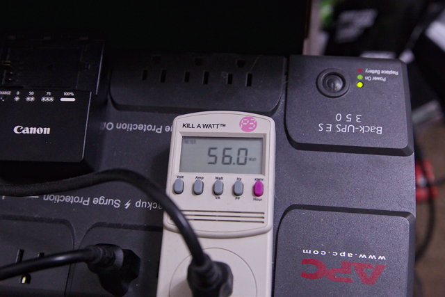
I am very happy with the numbers I’ve seen on my Kill-A-Watt meter. At idle, with a few virtual machines booted up, the new server consumes about 34 watts. The workload in the virtual machines has enough slow, steady writes that the 3.5” hard drives will never get to spin down. That pair of disks account for about 9 watts—that’s about 25% of the idle power consumption.

If you choose to build this server with only solid-state drives, then your power consumption would be quite a bit better than mine! I’m hoping that dm-cache will be able to cache some of that disk access that’s keeping the spinning media busy.

Power usage under load isn’t bad, either. The server stays just below 50 watts most of the time while running disk and CPU benchmarks concurrently, but with a few spikes up to 52 watts. For reference, my desktop computer uses over 120 watts at idle.

This is close enough to the J1900 at idle, and I feel that the 15 to 20 percent better performance of the AMD 5350 is worth the extra consumption under full load.

Moving these virtual machines from my desktop computer to my new power-efficient server means I can now turn off my power-hungry desktop while I’m asleep or out of the house. That would be a direct savings of over $30 per year. With the weather here in Texas, I’d probably save almost as much in air conditioning costs as well, with the ancillary benefit of having a cooler home office.

The conclusion

I’m very pleased with this energy-efficient server I put together. It easily met my energy consumption goals, and it has more than surpassed my CPU and storage needs. The AMD 5350 is a good little processor that doesn’t even break a sweat keeping up with full disk encryption on the fast Samsung 850 EVO solid-state drives.

I’m hopeful that dm-cache will work well. The server has been up and running for almost three weeks now, but I’ve been too busy with other projects to spend time playing with dm-cache. I’d like to write more about dm-cache and other topics related to this virtual machine server in the near future.

Do you have a server at home to host your virtual machines? It is relatively quiet and power efficient like this one, or is it a loud rack mount server with Xeon processors and ECC RAM like the one this blog lives on? Tell us about it in the comments, or come chat with us about it on our Discord server!

3D Printed Breadboard Spring Vise

| Comments

My friend Brian and I have been messing around with breadboards, Arduinos, and ESP8266 boards quite a bit during the past several months. We learned pretty quickly that it is difficult to keep the various boards you’re working with from flopping all over your desk, and it is even harder to line things up to take a decent photograph.

There are a lot of brackets on Thingiverse designed to hold a breadboard and an Arduino in place. I didn’t think it would be difficult to adapt one of those designs to also hold a tiny ESP-01 WiFi board in place as well.

Then I saw the awesome-looking Stickvise over at Hackaday.com. The Stickvise is quite versatile, but it is primarily used for holding circuit boards in place. The springs hold your part securely in the Stickvise while still allowing for parts to be swapped in and out quickly.

This gave me the idea of adding some spring-loaded vise jaws to a breadboard. I didn’t use springs, though. I used simple rubber bands.

Skipping to the completed breadboard “spring” vise

Here’s the final iteration of the breadboard spring vise. It works even better than I expected. I can load it up with Arduinos or other circuit boards and shake it around quite vigorously, and all the boards stay in place. I never thought it would be this sturdy, and still takes almost very little time and effort to insert or remove something from the jaws.

Breadboard Spring Vise with Various Boards

The entire breadboard vise assembly consumed less than 75 grams of ABS plastic. That is only about $1.25 worth of material.

Let’s go through some of the design process.

Offset rails

I wanted to be able to attach two vise jaws along each side of the breadboard. That means the rails that the jaws ride on can’t be directly across from each other. One solution to this problem would be to use different rail spacing on each side of the vise. I didn’t like this solution. I wanted to be able to print a single part that would work in any location around the breadboard.

I ended up offsetting the rails to one side. That way the rails wouldn’t touch when you spin the clamp around 180 degrees. I wanted to have a pair of jaws along each side of the breadboard, so I divided the length of each jaw into five sections. Each section can have a rail, a post for a rubber band, or nothing at all. The center section always gets a rubber band post. That way the posts are always directly across from each other.

Breadboard Spring Vise Showing Offset Rails

They say a picture is worth a thousand words.

Why are the rails shaped like triangles?!

Round rails were the first thought that came to my mind, but they wouldn’t print very well if they’re laying down flat on the print surface. Printing them standing on end wasn’t a good idea, either, because they’d be weakest in the direction where they needed to be strongest!

Square rails would print just fine. Unfortunately, the slots they’d be inserted into would have a bridge on top. That bridge might sag, and the rails wouldn’t fit well if they did.

Triangles have neither problem. They’ll print just fine laying down, because they’re flat on the bottom. They don’t have the bridging problem, because the sides are 60-degree angle.

Three-sided cylinders are problematic

I thought using a three-sided cylinder for the rails was a smart idea—it wasn’t. It would have been easier to work with the triangle if I knew the length of the sides or the height of the triangle. Instead, I knew the diameter of a cylinder. The diameter of a weird, three-sided cylinder. That meant I was often just guessing at dimensions until things looked right. I really hated doing that in OpenSCAD.

Spacing the rails

At first, I was barking up the wrong tree, and I was making things more complicated than they needed to be. I was trying to space up to five rails out equally along each jaw. That means I would need 10 slots in the base piece in order to mount two jaws on each side.

I had a lot of trouble getting the math to look right. When I finally did, I realized that it would be difficult to transfer this logic over to the base of the vise in order to carve out the slots. It would have required transferring the spacing from two sets of jaws over to the base, and that seemed too convoluted.

Breadboard Spring Vise

Instead, I did the math to evenly space 10 slots along the base piece of the vise. From there, it was easy to reapply that same math to the jaws.

Rails Vs. Slots!

On my first iteration of the vise, the rails were way too flimsy, and the slots were way too small. I really wanted to know how viable this design was, though, so I spent five minutes with some sandpaper to force everything to fit together.

The vise was able to do its job, but the rails were quite flexible. I only had to adjust one variable to make the rails and slots bigger, but they still weren’t going to fit.

I bumped up the width of the rails from 5mm to 8mm. That increased the cross sectional area by over 2.5 times, and it was definitely beefy enough now. I increased the size of the slots by an additional 10%.

I should mention something here. The triangular slots only have a ceiling near the outer edges. I did this to save on print time and materials. I just had to make sure the the walls were high enough to hold the outside edges of the rails in place.

In part due to my measurement guesswork regarding the “diameter” of the 3-sided cylinders, I forgot to increase the height to compensate for the taller rails. They weren’t held in place at all, so they were just flopping around in there.

I chopped out a small corner of the breadboard vise, and I printed some test parts are various sizes. I zeroed in on a good size on my second test.

Always test a small section

The breadboard spring vise has 10 rails that need to fit into 10 slots. I should have carved out a single rail and a single slot piece right from the beginning. It is easy to do, and it would have saved me quite a few hours of printing time.

Download my Breadboard Spring Vise

The OpenSCAD source for my breadboard spring vise along with STL files are available for download at Thingiverse and Github.

If you can’t print your own, you can buy a Breadboard Spring Vise at Tindie.com!

Would I Still Buy a QNIX QX2710 in 2015?

| Comments

I woke up last week, sat down at my computer, and one of my QNIX QX2710 monitors wouldn’t wake up. It was yet another in a series of small, unlucky happenings that have been occurring here for the last month or so. Fortunately, I know exactly what to do when a monitor dies—replace it!

My QNIX Monitors at My Desk

I almost immediately placed an order for another QX2710, but I decided to investigate the market first. It has been almost two years since I bought these monitors, and I’ve known the 27” QNIX to be a great value for a lot longer than that. I haven’t been paying as much attention lately, but 4K monitors have gotten quite affordable. Maybe there’s something now that fits my needs better than the QX2710.

Is it time to move up to 4K (UHD)?

It isn’t time for me to move up to 4K yet. The first problem is all of the reasonably-priced 4K monitors are using TN panels. I don’t ever want to go back to TN. I prefer the vibrant colors and large viewing angles of my QNIX’s PLS panels.

Also, all of the currently available 4K monitors are limited to a refresh rate of 60 Hz. After gaming for so long at 120 Hz, there’s just no going back. First-person shooters just look so much smoother at 120 Hz!

QNIX QX2710 at 120 Hz

Even if I could tolerate downgrading to 60 Hz for gaming, I’m not convinced that my gaming machine has enough horsepower to maintain 60 frames per second at 3840x2160. My machine struggles to maintain a constant 120 frames per second in Team Fortress 2 at 2560x1440. When things get busy, it drops down almost all the way to 60 frames per second.

Borderlands 2 and Borderlands: The Pre-Sequel spend as much time under 60 frames per second as they do above. I don’t think either game would run very smoothly at 3840x2160.

These concerns of mine shouldn’t worry you if you’re not as interested in gaming as I am!

Samsung 28” 4K U28D590D

One of the first monitors I looked at was the Samsung U28D590D. It is a 28” monitor with a 3840x2160 TN LCD panel. They’re available at Amazon for under $500 and at eBay for under $400. That’s only about $100 more than a QNIX QX2710, and that buys you a name brand and more than double the pixels.
I only game on a single monitor, so I could have replaced my dead QX2710 with a 28” Samsung 4K. The biggest problem there would be the huge differences in DPI between the two monitors. The Samsung has a DPI of around 150, while the QNIX has a DPI of around 108. That means that a window moved from the Samsung to the QNIX would look almost 40% larger.

I’ve used a 15” laptop plugged into a 24” monitor. I’d have the same problem with a 4K monitor and a 1440p monitor. I’d end up doing work on the 4K and playing games on the 1440p. That’s not appealing to me.

The pixel density upgrade of the 28” UHD monitor would be nice, but my monitors sit just out of an arm’s reach, so my 27” QHD monitors should almost qualify as “retina” by Steve Jobs’s definition.

Crossover 40” 4K 404K

The Crossover was a tempting and interesting surprise. It is a 40” monitor with a 3840x2160 TN LCD panel. At around $700, the big Crossover monitor costs a lot more than the QNIX, but it would allow me to scale down to a single monitor AND increase my pixel count at the same time. The Crossover 404K was the only monitor that truly made me question whether I should buy another QX2710.

I was worried about the physical size. The Crossover is 12” wider than a 27” monitor. This is pretty close to ideal, because that’s about the limit of my viewing area without having to turn my head.

The part that I’m less excited about is that the Crossover is 6” taller than a 27” QX2710. As far as I’m concerned, my QNIX monitors are pushing the limits of comfort on the vertical axis. The Crossover would end up sitting just a few inches off the desk, and I’m not so sure I’d be happy with that.

I also had some concerns about using this monitor for gaming. Just like with the Samsung 4K, I’d be unhappy about downgrading to a 60 Hz TN panel, but I might be willing giving up my 120 Hz gaming to finally have a single, huge display!

The Crossover 40” has roughly the same pixel density as my QNIX 27”. That means all my terminal and text editor fonts would look nearly identical on either monitor from the same viewing distance. The difference is that the Crossover would give me over 8 million pixels on a single monitor vs. 7.2 million pixels across TWO QNIX QX2710 monitors.

If I didn’t know or care about high refresh rate gaming, this would definitely be the monitor to buy. I could fit miles and miles of terminals, text editors, and web browsers on this thing!

Asus 27” MG MG279Q

There were no QHD IPS or PLS monitors with 120 Hz refresh rates available when I bought my first QNIX monitors. This is no longer the case. The ASUS MG279Q is the same size and resolution as the QNIX QX2710, but the ASUS comes from the factory supporting a 144 Hz refresh rate!

If you are looking for a trusted, name-brand monitor for gaming, I don’t think you can do any better than the ASUS MG279Q. High refresh rates are simply amazing when playing first-person shooters, and all games look great on an IPS panel.

The ASUS MG279Q wasn’t a good choice for me. I can buy two QNIX QX2710 monitors for less than the price of the MG279Q. That means I’d want to buy two 27” QHD monitors instead of one!

I don’t want to pay more than double for a 20% higher refresh rate, and I’d prefer to have a pair of identical monitors on my desk. Even if it means I’ll have to debezel a new QX2710 shortly after it arrives.

LG 34” 34UM95C 21:9 Ultrawide

I really like the idea of ultrawide monitors, and the 34” LG 3440x1440 monitor seems like it would be the ideal size. The 34” LG ultrawide is about the same height as a 27” 2560x1440 monitor, but it is an extra 880 pixels wide. That happens to be about how much of my two monitors I can use without having to turn my head.

Unfortunately, I think the LG 34UM95C costs too much. At over $800, it costs more than either the 40” Crossover monitor or three QNIX QX2710 monitors. That’s just too much of a premium for 880 more horizontal pixels.

LG has smaller 21:9 monitors, but I don’t find them very interesting. Their 29” 2560x1080 monitor is the same width as a 27” 2560x1440 monitor, but with 360 pixels missing from the bottom. You end up paying extra for less monitor with the LG 29” ultrawide!

QNIX 27” (QX2710)

I may have thought about buying the Crossover 40” 4K, but I didn’t think about it for very long. I ended up ordering another glossy QX2710 from Amazon. I bought the last two through eBay, and they arrived from overseas very quickly, but not Amazon Prime quickly. It cost me a little more this way, but I was in a hurry!
Why did the QX2710 fail?

One of the unlucky things that happened to us last month was our air conditioning died. It took much, much longer to get the problem resolved than I would have liked, and my home office was up over 95° for several days. It is normally around 72° in here.

I don’t know that I can blame the failure on the additional heat, but I do have a reason for bringing it up. On one of the hottest days, I noticed a line of flickering green pixels down the center of that monitor when visiting a dark gray website. The first thing I thought was that overclocking that monitor to 120 Hz must be pushing this monitor right to the limit if the extra heat is pushing it too far.

I clocked that monitor down to 110 Hz, and the problem went away. I hadn’t thought about it again. It was nice and cool in my office the morning after the air conditioning was finally repaired, and that’s also the morning that the monitor stopped working.

I’m not sure if there is a correlation between the monitor failing and the heat, but I don’t trust coincidences. One of these days I’ll crack the dead monitor open to check for simple things like bad capacitors. The control board is now sealed in with JB Weld, so I’ll have to cut my way in. I’m not in a hurry to do that!

Why would you buy another one after this trouble?

Even with a failed monitor, I’m confident that I made the right choice when I bought these monitors. The first two monitors cost me $651. A pair of the least expensive name-brand 27” 1440p monitors would have cost me around $1100 at the time. Even after spending almost $300 on a replacement this week, I am still ahead by $150.

I still feel that the QNIX QX2710 is still one of the best values out there. There are other comparable name-brand monitors available today, and they don’t cost three times as much now. The 27” ASUS PB278Q is only about $150 more than the QNIX QX2710, and the ACER K272HUL is less than $100 more.

Update: A Problem With The New QX2710!

They’ve redesigned the QX2710. I finally got a chance to take apart my new QX2710 to remove the bezel, and I was pretty disappointed when I got inside. The QX2710 no longer uses the same metal frame around the LCD panel, and there is a new circuit board extending almost an inch below the screen.

I think debezeling would work as well as before, but it won’t work well in my case. I wanted to have two matching, debezeled monitors again, and the new monitor looks nothing like my old one. I removed the last remaining piece of the monitor’s stock stand, and I put it back together for now.

There are some other changes as well. The panel is different, and the color output doesn’t quite match the old models. I was able to fiddle around with ICC color profiles, and they look close enough for me now.

I’ve been reading rumors that the new QX2710 glossy monitors can no longer be overclocked. They say if you do overclock them that they will just skip frames. My new monitor made it to 110 Hz. I do not have a good enough camera to verify that there is no frame skipping, but I’m quite confident that there isn’t any.

The simple act of quickly dragging a window around the screen looks much smoother at 120 Hz than it does at 60 Hz. I monkeyed around with the refresh rates on both monitors, and I dragged windows around all over the place. I’m pretty confident that neither screen is skipping frames. One of these days, I’ll end up buying a DSLR, and I’ll be able to confirm this!

Old, better model QX2710 at 120 Hz New model QX2710 at 102 Hz

I finally bought a DSLR, and I was able to test both of these monitors for “frame skipping” and “frame doubling.” I am happy to report that they’re both able to overclock flawlessly. When I set the shutter speed to 1/400 or faster, the camera shows a single white bar. This shows that there is no “frame doubling.”

The pictures above were taken with a shutter speed of 1/60. At that speed, you can see some light from the next and previous bars. This shows that there is no “frame skipping.”

I have yet to decide what to do about this situation. The new monitor is just fine, but my desk looked so much nicer with a pair of matching, debezeled monitors!

Update: ICC color profiles for differing QX2710 monitors

Aside from my bezels no longer matching, the biggest problem with running an old QX2710 right next to a new QX2710 is the big difference in their color output. I think both monitors look just fine on their own, but the differences were driving me crazy.

I downloaded just every ICC profile from the QNIX Monitor Owner Club forum post, and I tried them using them in all sorts of combinations. I just couldn’t tune in any combination I was happy with. The new monitor was limited to about 110 Hz at best, and that was just so much brighter than the old monitor at 120 Hz. I was more than a little tempted to buy a color calibration device.

I’ve come to a compromise that is close enough for me. I found a pair of color profiles that were close, but my old QX2710 was still too bright. I tried adjusting the brightness with the controls on the monitors, but that didn’t get me far enough.

I am now running the old monitor at 102 Hz and the new monitor at 96 Hz. They’re definitely not identical, but they’re pretty close. Close enough that I stopped noticing the difference. At least until I started writing this update!

These are the ICC color profiles I’m using.

My First Year of 3D Printing

| Comments

I bought my 8” Prusa i3 printer almost a year ago. I had been interested in the idea of owning my own 3D printer ever since the first time I saw a video of the old MakerBot Cupcake in action. I thought it would be neat to be able to download designs from the Internet and print them in my own home, but I didn’t think that would be a good enough reason to own my own printer.

Since it has been almost a year, I thought it might be fun to talk about where I started, and just how far this journey has taken me. My goal was to be able to design and print my own objects, and I’ve definitely exceeded my expectations. It took roughly ten months to go from printing objects downloaded from Thingiverse to designing and printing my own parametric, articulated objects using OpenSCAD.

The first week of 3D printer ownership

The printer I bought was used, and it was already assembled when I picked it up. I was able to print things that I downloaded from Thingiverse on the first day. This was very exciting, but the print quality was quite low. I didn’t care! It was exciting just to see anything come out of the printer on my first day!

Glow In The Dark Space Invaders

The gentleman that assembled my Makerfarm Prusa i3 didn’t do a very good job. The belts were loose, and the bed eventually fell off during a print. The cabling job is also a complete mess. I corrected the first two problems early on, and my printing results improved dramatically, but the cabling is still a mess. Thankfully, the rat’s nest of cables is all off to one side, and it doesn’t cause any problems. I doubt that I’ll bother trying to clean that up until it starts causing trouble.

My printer was running almost nonstop during that first week. I was printing all sorts of random parts from Thingiverse, and I was printing lots of calibration objects in an attempt to improve my slicing settings.

The start of the second week – designing my first part with Blender

I’m very proud of the progress I made early on. I had my first custom part designed and ready to go within the first week, and I had the first prototype printed on my eighth day. That first part may have only been a platform on top of a simple cylinder, but I was ridiculously excited about it.

You can see all the newly beveled edges in Blender The front wall is thick, sturdy, and just tall enough The front overhang is a bit rough, but none of the filament was sagging!

This was the first time ever that I created something on a computer, and a real-life object slowly appeared next to me. And even more exciting to me, that object fit perfectly and snugly inside another real-world object that I already had in my possession.

This was the moment when I truly realized how revolutionary 3D printing is. With my extremely limited abilities, I was able to create a very precise object in the real world, and this was only the beginning!

The next eight months – More complex objects

I designed and printed quite a few objects over the next eight or nine months. All but one of those objects were designed using OpenSCAD. I’ve already written about most of these designs, so I’m only going to mention some of the highlights here.

The parts I designed range from small, simple parts like the keychain flash drive connector for my friend’s Keysmart keychain, to more complicated objects like the mount for my FiiO Andes USB DAC, to larger pieces like the cable cover for my monitor stand.

Monitor Stand Cover Animation

In the early days, it took many hours to design and perfect my tablet keyboard stand. These days, I can bang out a design for a simple camera mount in fifteen or twenty minutes. I’m very excited about how far I’ve come!

Ten months – Multipart articulated objects

During the first ten months or so, all of the objects that I designed were single, solid pieces. During that span of time, my friend Brian and I talked a lot about the possibility of designing car mounts for cell phones. He’s been using the excellent mounts from ProClip, and when Brian upgraded from the Nexus 5 to the Nexus 6, he needed a new mount.

He only needed to replace the piece of the mount that actually holds the cell phone, and I didn’t think it would be difficult to design it. I can’t recall exactly why, but we didn’t get around to printing one before he ordered one.

Then, not too long ago, I was toying with the idea of mounting one of my old Android phones on my 3D printer to broadcast live print jobs. There were some technical limitations preventing me from doing this, but I knew I’d need some sort of mechanism to aim the phone’s camera at the print.

Brian’s ProClip mounts have a neat little ball joint between the mount and the phone that allow it to tilt and swivel. I knew that I could manage to create something with similar flexibility, but I didn’t think it would be possible to print anything like that ball joint. The ProClip’s injection molded ball joint is quite small, very sturdy, and it moves smoothly.

Since I didn’t think the ball joint would be possible, I figured that the only option would be a simple swivel base attached to a single U joint.

The Tilt/Swivel Ball Joint

I decided to have a go at designing the ball joint, even though I didn’t think it would work. I was very wrong. It was simple to design, and works better than I ever imagined! The joint is made from three pieces of plastic connected together with a single M3 screw. The more torque you put on the screw, the harder it is to move the joint.

I had the first prototype designed in about 20 minutes, and I printed it the next day. It worked really well, but it was just the joint. It didn’t have any mounting points on the edges, and it didn’t have much extra room so that you could get your fingers on it to move it around, but it worked!

I went straight to work modifying the design. I made the “top” piece of the joint slightly taller, and I wrote some code to generate four mounting points. It was just another 20 minutes of work, and my new joint complete with mounting brackets was printing!

It isn’t as smooth as ProClip’s joint. Due to the nature of FDM 3D printing, there are small ridges circling around the parts of the joint. This means that it takes less force to swivel the joint than it does to tilt. It felt a bit crunchy at first, but a few seconds of sand-papering made it feel infinitely better.

Was the 3D printer worth the money and effort?

The Prusa i3 3D printer was worth every penny. I’ve had a lot of fun during the past twelve months, and I have learned a lot. I haven’t printed $600 worth of useful objects yet, and I don’t feel that I have to in order to justify the expense of owning the printer. I would enjoy someday reaching that point, because it would be fun to brag about, but I’m not in a hurry to get there.

I’d be very surprised if there is a faster way to get from thought to reality than owning a 3D printer. I recently came across the old hack of attaching a USB webcam to an inexpensive, articulated lamp from IKEA. I thought it was a great idea, but I wanted to improve on it. I wanted to attach the arm to the top of my monitor stand.

We stopped by the local IKEA before dinner, and we picked up a couple of IKEA’s TERTIAL lamps. We came home after dinner, and I unpacked the lamps and took a couple of quick measurements. It only took about 20 minutes of work in OpenSCAD to put together a usable mounting bracket for the arm. I fired up the printer the next morning, and I had a working part in my hand in about two hours.

Close up of the pieces The mounting bracket attached to the monitor stand The assembled webcam arm

The adapter that connects the monitor stand to the IKEA lamp is very simple. I probably could have made something that would do the same job by taking a drill and a saw to a large diameter dowel from Lowes, but I couldn’t have produced anything this clean by hand in the 20 minutes it took me to model the part I used. Maybe I could have made something decent by hand in the two hours my part took to print, but that would be cheating. I was working on other things while the printer was running!

Do you own a 3D printer? What do you use it for? Do you mostly print your own models, or do most of your prints come from a site like Thingiverse?

The Blu Studio 6.0 LTE Android Smartphone

| Comments

I’ve been contemplating the idea of making some changes in my portable and mobile worlds for quite some time. For a long time, I only had a laptop and a cell phone. Life was simple then, and there wasn’t much overlap between the two devices. Now I have a desktop computer, a giant 18.4” laptop, an 8.3” Android tablet, and a 4.7” Android phone.

There’s a lot of devices there with overlapping functionality. I’ve been thinking about replacing my tablet and smartphone with a single device ever since my friend Brian bought his Nexus 6. The trouble is the Nexus 6 isn’t much of an upgrade for me. It is a much better phone than my Nexus 4, but in all honesty, I barely use my phone unless I’m traveling.

Nexus 4 vs. Blu Studio 6.0 LTE vs. LG G Tab 8.3

It didn’t seem worth $460 to replace a device that I only use for about an hour each week. It also didn’t seem worth spending that same $460 to limit myself to a smaller tablet, especially since I use my tablet for an hour or two every day.

Sony Xperia Z Ultra — The wrong phone for me

I’ve had my eye on the 6.4” Sony Xperia for almost six months. Aside from the screen, it would have been a slight upgrade over my Nexus 4. The huge 6.4” screen is nearly as large as my old Nexus 7. I read plenty of books on my Nexus 7, so I’m pretty confident that I could use a 6.4” screen for just about anything.

There were two problems with the Z Ultra. It is an extremely tall phone at 6.9” high. I’m not so sure that would fit well in my pocket. It also doesn’t help that the price on the Xperia Z Ultra has gone up by about $80 since the last time I looked at it.

Blu Studio 6.0 LTE

I’m not entirely sure where I discovered Blu, but I’m glad that I did, even if their product names leave a lot to be desired. I zeroed right in on the Blu Studio 6.0 LTE. Don’t get it mixed up with the extremely underpowered Blu Studio 6.0 HD. The Studio 6.0 LTE has twice as much RAM, a higher resolution display, four times the flash, and an LTE radio.

I’ve spelled out the complete name of the Blu phone almost every time I’ve mentioned it in this post. I’m too worried that someone will mistake it for a different Blu phone!

The specs on the Blu Studio 6.0 LTE are quite reasonable. On paper, it is pretty much a Nexus 4 with a much bigger, higher resolution screen and a slower GPU. That isn’t exactly an upgrade for me, but I wouldn’t call it a downgrade, either. The Blu phone also has twice as much flash as my Nexus 4 and a MicroSD slot.

The Blu Studio 6.0 LTE only costs about $200 shipped. That’s less than half the price of the cheapest Nexus 6 I could find, so it was inexpensive enough that I didn’t have to hesitate. Even if I hated it, I could easily stomach the loss.

First impressions out of the box

I was more than a little worried when I pulled the Blu Studio 6.0 LTE out of the box. I always tell people that I don’t want my phone to be made of fancy, expensive materials like titanium or aluminum. I want my phone to be as light as possible. If a plastic phone is lighter, and it is still sturdy enough to survive living in my pocket, then a plastic phone is what I want.

The phone felt REALLY light. It ships without the battery installed, and it felt way too light and very oddly balanced. Also, the thin plastic cover on the back of the phone feels really flimsy without the battery.

The Blu Studio 6.0 LTE Battery is HUGE

Once I put the battery in, things improved dramatically. The phone is very well balanced, and it weighs about as much as any other phone with a 6” screen. The 3200 mAh battery in the Blu Studio 6.0 LTE is nearly as wide as the Nexus 4!

I’m a fan of the finish of the back cover. It has a slightly rubbery feel to it, so it doesn’t want to slide right out of your hand. It is the same sort of finish on the back cover of my old HTC Dream, the top of my wireless gaming mouse, or the Amazon Fire TV remote control. The glass on the back of my Nexus 4 might look better, but the Blu Studio 6.0 LTE feels much nicer in my hand.
The phone comes with a silicone case, but I never use cases, and I have absolutely no interest in making my giant phone any bigger.

It isn’t exactly a Nexus 6

The Blu phone isn’t a Nexus 6, and I didn’t expect it to be. I knew most of the shortcomings before even placing my order, but I wasn’t sure how much of an impact most of these shortcomings would have.

The Blu Studio 6.0 LTE has a lot going for it. It is a bit light, a few mm taller, and a couple mm narrower than the Nexus 6, and they both have 6” screens and a screen-to-body ratio of over 74%. In fact, the Studio 6.0 has a slightly better screen-to-body ratio, AND it has three physical buttons instead of software buttons like the Nexus 6. That buys the Blu over ¼” of extra screen real estate.

Blue Studio 6.0 LTE Bandwidth Test

The Blu Studio 6.0 LTE phone has a very limited number of LTE bands, but they happen to be the bands you need for T-Mobile. My friend Brian and I both use T-Mobile, and we did some random bandwidth tests the other day while driving around town. My Blu phone had comparable performance to his Nexus 6 each time we tested, and I usually even came out ahead by a couple of megabits per second.

It isn’t exactly a Nexus 4

I don’t want to say that the Blu Studio 6.0 LTE is slower than my Nexus 4. They feel pretty comparable most of the time. I can quickly flip between apps like Hangouts, Janetter, Feedly, and RedReader in a fraction of a second on either device, and scrolling around in those apps feels just fine.

Sometimes the slow GPU in the Blu Studio 6.0 LTE becomes noticeable. When moving bubbles around in Link Bubble, the frame rate can get pretty low. This doesn’t slow me down, but I can definitely see the bubble lagging behind my finger.

Blu Studio 6.0 LTE vs Nexus 4

The Blu Studio 6.0 LTE fared surprisingly well in an AnTuTu benchmark. It managed to outscore the Nexus 4 in every test except for the two GPU tests, and the Blu isn’t too far behind the Nexus 5. That slow GPU makes the UI a little less buttery, and it might keep me from playing some higher end games.

Luckily for me, the GPU is more than fast enough for the sort of games I play! At the moment, I’m addicted to You Must Build A Boat.

KitKat forever!

The Blu Studio 6.0 LTE ships with Android 4.4.2 KitKat. That’s not exactly cutting edge, and I don’t expect to ever see an update to Lollipop. For my own purposes, I’m not too concerned about this. I’ve been running KitKat on my Nexus 4 for ages. I am shackled pretty tightly to a couple of Xposed Framework modules, and they only recently started working with Lollipop.

I had some trouble rooting the phone. Towelroot just kept telling me that my device was unsupported. Lucky for me, once Blu’s small OTA firmware update was installed, Towelroot had no trouble rooting the phone.

I can’t say how well being stuck with KitKat will work out for you, but some Xposed Framework modules provide me with most of the Lollipop-related functionality that I would miss. For now, I will leave it at that. I think Xposed will need a blog post of its own.

GPS

I didn’t see any mention of the quality of the GPS in the Blu phones. I was bitten by a huge GPS downgrade a long time ago when I upgraded from the HTC G1 to a Samsung Galaxy S, so I was a little worried about this.

The first time I took the Blu Studio 6.0 LTE out of the house, I just couldn’t get a GPS lock. I checked the settings, and made sure all the GPS-related options were activated, and I rebooted the phone. As soon as I did that, Google Maps instantly made a lock, and it followed us perfectly to our destination.

I’ve navigated several times since then, and I haven’t had any more trouble. My little car icon does a very good job of following the road on the map. It hasn’t taken any weird journeys off on nearby roads, like my Samsung Galaxy S used to often do.

I’m pretty confident that the first failure was a fluke. I’ll be sure to report back here either way!

I really miss Gorilla Glass

As far as I know, none of the phones from Blu ship with anything like Gorilla Glass. They have regular glass, and my Studio 6.0 LTE came with a screen protector installed to cover the cheap glass. I hate it. I really, really hate it.

Your finger doesn’t slide as smoothly on a piece of plastic, and the plastic attracts all of the oils from your skin. I can use a device with Gorilla Glass for weeks and never notice how dirty the screen is, at least when looking directly at it. With the stupid screen protector, I could see a smudge the first time I touched the screen, and it just got worse from there.

I’m tempted to rip the screen protector off, but I know that I can’t apply the spare protector without ending up with bubbles and dust underneath.

Is 2 GB of RAM enough?

My short answer to this question is yes. If you trust me on this, you can skip this section of the post!

I could write an entire blog post on this topic, but I’ll do my best to summarize my thoughts. On my devices with 2 GB of RAM, Android is able to keep more than a dozen services running, and more than a dozen apps cached at any given time. I can easily flip between my half dozen most commonly used apps quickly and efficiently, even after I’ve been doing some heavy web browsing.

When you run out of RAM, Android starts kicking some of those cached apps out of RAM. Once those apps are shut down, you’ll have to wait for them to start back up the next time you want to use them. The less RAM you have, the more waiting you have to do.

You’re probably waiting around for apps to reload quite often if your device only has 1 GB of RAM. In my own experience, I don’t see this happen all that often on my 2 GB devices. I usually only notice it after playing a big, heavy game. Of course, your mileage may vary!

And the real question is

Is the Blu Studio 6.0 LTE worth $206?

In my opinion, the answer to that question is yes. It is most definitely worth $200. I could buy two of these phones instead of a single Nexus 6, give one to my wife, and still have $50 left over to go to dinner. If you want a giant clown phone, I doubt you can do much better than the Blu Studio 6.0 LTE without spending at least twice as much.

Pros:

  • Physical home, back, and menu buttons means more screen real estate
  • 2 GB of RAM
  • Fast enough (just barely!)
  • MicroSD support
  • 6” 1080p screen
  • Easy-to-open back cover with user replaceable battery
  • T-Mobile LTE bands

Cons:

  • No Gorilla Glass
  • Slow GPU
  • Only T-Mobile LTE bands
  • Mediocre camera
  • Stuck with KitKat
  • No wireless charging

At $200, there really isn’t much to complain about. The phone feels solid, and it doesn’t creak or squeak. It even has a user replaceable battery, and you don’t need a set of spudgers to get the case open. All you need is your fingernail! I’ve really missed phones that are this easy to take apart!

The Blu Studio 6.0 LTE seems to use the same chipset as the $179 Moto G from Motorola. The Blu has a bigger screen, twice as much RAM, and a larger battery than the Moto G. The extra $25 you have to pay for the Blu phone buys you a much more usable Android smartphone.

I’m much happier carrying a phone with a 6” screen, but I’m not yet entirely convinced that I won’t end up missing my LG G Pad 8.3. Only time will tell. I did have enough confidence in this plan of mine just two days after the new phone arrived. I’ve wiped my old phone and tablet, and I sent them to my parents.

Do you have a Blu Studio 6.0 LTE, or any other Blu phone? What do you think of yours? Did I leave anything important out of this post? What else would you like to know about the phone?

The E-Blue Mazer II Wireless Gaming Mouse

| Comments

I’ve been using wireless mice for most of the last ten years. During most of the time, I used my old Logitech MX900 Bluetooth mouse. The MX900 was a very power-hungry mouse; I had to make sure to put it in the dock every night, or else I had to swap the batteries every few days. Being power hungry was what made him suitable enough for playing first-person shooters.

I tried other wireless mice before buying the MX900, but they liked to take short naps fairly often. If I was playing a game, and waiting around a corner to ambush someone, the mouse might be asleep and cost me valuable seconds. The MX900 didn’t have that problem, so I was willing to put up with the need to keep a couple sets of Eneloop batteries around.

My Desk

By the time I replaced my laptop with a new desktop machine, the MX900 was really starting to feel old. The battery door was busted, the skates were starting to fall off, and an 800 DPI mouse starts to seem less smooth when gaming at 2560x1440 at 120 Hz. I figured it was time for an upgrade, so I picked out a random, inexpensive 1600 DPI wired mouse.

It was a fine mouse, but I had forgotten how annoying it is having a wire. If you just drop the wire behind your desk, gravity sometimes pulls at your mouse. If you drop it down the desk’s grommet, you’re sometimes fighting against the cable. In the end, I decided to velcro the mouse cable to my monitor stand. It worked well enough, but every so often I would run out of cable. I have a very smooth desk, and I don’t use a mousepad. With a wireless mouse, I can circle strafe in the same direction for a long time before running out of surface. Running out of cable was a different matter.

My friend Brian bought a fancy wireless mouse recently, and I was immediately jealous. I wanted a wireless mouse again, but the mouse he chose has one of the same failings as my old Logitech MX900: the batteries only last a couple of days. That was something I didn’t want to go back to, so I started doing some research.

The E-Blue Mazer II

The mouse I kept coming back to during my research was the E-Blue Mazer II wireless gaming mouse. It seems to be modeled to imitate the look of several of the mice that Razer makes, but it is sold for a fraction of the price. This alone was a bit worrisome, but optical mice are made from simple components that were already inexpensive a decade ago. There’s absolutely no reason that you can’t sell a quality wireless mouse today for $25, so I wasn’t going to use this as an excuse to cross this mouse off my list.

E-Blue Mazer On My Desk

The specifications and reviews led me to believe that the E-Blue Mazer II would fit all of my requirements. It is wireless, it can be set as high as 2500 DPI, and several reviews claimed that a single set of AA batteries would last from several months to almost an entire year.

I couldn’t see any reason not to pull the trigger on a mouse that costs less than $25. I opted to pay an entire extra dollar for the version that lights up. I don’t ever plan to use the lights, but I thought they’d make for better photographs!

First impressions

The E-Blue Mazer II comes in impressive packaging for a sub-$25 mouse. It comes in a solid, reusable plastic case. It is the sort of case that I would store a handful of Arduinos and related electronics components inside. When you open the box, you’ll see the mouse, AA batteries, and wireless USB dongle staring back at you. It is much nicer than the usual blister pack most inexpensive mice are packaged in.

E-Blue Mazer Packaging

There were a lot of reviews complaining that the E-Blue Mazer II is too large. I was happy to hear this, because I have fairly large hands. The one fact that I don’t recall reading is how short this mouse is. I bet it is nearly ¼” shorter than the average mouse. This was weird for the first few minutes, but I soon stopped noticing.

The range on the wireless dongle isn’t the best. I had the dongle directly into my desktop computer at first, and my computer is on the floor next to the desk. The mouse seemed to work fine at first, but then I picked it up and moved it. Whenever I did that, the mouse pointer would jump to the upper left corner of my screen. Relocating the dongle completely solved this problem for me.

This isn’t too surprising to me. My desk is made of heavy, thick MDF. I’ve had problems with various Bluetooth devices in the past. I just assume that 2.4 GHz doesn’t penetrate it very well.

Don’t forget to unwrap the skates

The mouse worked just fine out of the box, and I used it for almost two weeks before I noticed something very important. There is a thin layer of protective plastic over the mouse’s Teflon feet. The plastic was smooth enough that the E-Blue Mazer could slide across my desk just as nicely as any other mouse I’ve owned.

When the Teflon skates make contact with the desk, though, the mouse slides around with significantly less effort. So don’t forget to peel off those thin protective stickers!

One month of daily use

I have very little to complain about so far. I’ve probably played two dozen hours of Team Fortress 2, and the mouse has been working admirably. The mouse is comfortable, the buttons only require a soft touch to activate, and the weight is quite nice. Most of the weight is in the AA batteries, and they’re very low and directly below my knuckles. That’s probably about as close as a mouse can get to being “mid-engine.”

I’m still using the generic batteries that came with the mouse, and they’re still going strong. I popped one out and tested it with my multimeter, and it is still reading a little higher than 1.5 volts. The E-Blue Mazer II stays completely awake while you are using it, but it shuts itself off if you don’t touch it for about five minutes. After it shuts down, you have to hit a button to turn it back on.

This was annoying at first, but I realize this is how you make the batteries last several months. I’d much rather have to click my mouse when I sit down than have to swap batteries every few days. The mouse rarely falls asleep while I’m working, but I do occasionally spend more than five minutes writing without ever touching the mouse.

The verdict

I would definitely buy the E-Blue Mazer II again. In fact, I plan to order a second one to keep in my laptop bag since they are so inexpensive. The second mouse will most likely be the model that doesn’t light up

I will come back to this blog post when I have to replace the generic alkaline batteries with a set of Eneloops, but I don’t expect that to be any time soon.

Do you have a wireless gaming mouse? I’d love to hear what you think of your gaming mouse, or even your E-Blue Mazer II. Please feel free to leave a comment!

A 3D Printed Cable Cover For My Monitor Stand

| Comments

Immediately after installing my monitor stand, it was obvious that I needed a good way to hide the cables that were routed out the back. Most people that use these stands wouldn’t see the cables, because they’re sitting directly in front of the stand. I am sitting at an L-shaped corner desk, so I am seated in such a way that I can see around the back.

The untidy mass of cables My desk looks much cheaner now

This seemed like a perfect job for my 3D printer, so I fired up OpenSCAD, and I got to work designing something that would hide these pesky cables.

I had some problems tuning in the final version

I started designing this object back in November—nearly six months ago. I had the first test print finished in December, and it came out surprisingly well. That original test piece is currently attached to my friend Brian’s monitor stand, and it is working well enough. I wanted to improve on that design, though.

I ran into some trouble, because I left town for almost six weeks. By the time I returned home, none of this was fresh in my memory. I didn’t remember the precise changes that I wanted to make, and being away from the code for so long made it harder to spot a major mistake.

Monitor Stand Animation

I had accidentally used the poleDiameter variable where I should have used the baseToBack variable. These two variables represent two very real world dimensions, but they were close enough that they didn’t throw the printed part too far out of whack.

I changed the baseToBack value at least three times before realizing that it wasn’t having the intended effect. Remember to always pay close attention to the variables you’re using!

You can download the OpenSCAD source code for this part at GitHub.

Designing to integrate with a real world object

Creating a 3D printed part that snaps into an existing, real-world part can sometimes be quite an easy task. All you have to do is create a model of important parts of the exiting object, and use your modeling tools to remove the difference of the real object from your new 3D printed part.

In the case of the monitor stand, this was mostly very simple, since it is simply an easily measured cylinder perpendicular to a flat, square bracket.

There was one aspect of my design that involved some guesswork. I wanted to 3D print some teeth that would grab on to the inside of the opening where the cables flow out. Measuring the width of the opening was easy. Guessing how much wider I needed to make the teeth for a reasonable friction fit seemed harder. Too tight, and the clips would break off. Too loose, and the cover wouldn’t stay in place.

Variables used in the examples

There’s a whole slew of variables defined at the beginning of the full OpenSCAD source code of this object. I’ve left those variables out of the example code snippets, but you’ll need to add those variable definitions to your OpenSCAD source file if you want to follow along.

1
2
3
4
5
6
7
8
9
10
11
12
13
14
15
16
17
18
19
20
$fn=100;  // Increase resolution of curves
poleDiameter=48.3;  // 1.9"

baseWidth=100.6;    // 3.960"
baseToBack=57.3;

centerToBack=poleDiameter/2+baseToBack;

cablePass=19;
cablePassHeight=40;

holeWidth=28; // 1.130"
dooberHeight=25;
heightToHole=60; // guesstimate

snapHeight=1.4; //guesstimate
snapWidth=1.4;

thickness=3;
height=124; // 5.0"

If you paste this code into the top of your OpenSCAD source, then you should be able to paste in any of my example code snippets and see exactly what I do.

Step 1: I had to start somewhere

Step 1 - I Had To Start Somewhere

1
2
3
cylinder(r=poleDiameter/2, h=height);
translate([0,baseToBack,thickness/2])
cube([poleDiameter+thickness*2, cablePass, thickness], center=true );

I wanted to create a smooth shape that would start above the wire opening, and stretch down to the back of the stand, and cover the wires until they were hiding neatly behind the desk.

I created a cylinder to match the vertical part of the stand, and I placed a small rectangular box to represent the base at the rear of my new cable cover. These were the starting points needed to be connected together.

Step 2: Creating a hull

Step 2 - Using a Hull

1
2
3
4
5
hull() {
    cylinder(r=poleDiameter/2, h=height);
    translate([0,baseToBack,thickness/2])
    cube([poleDiameter+thickness*2, cablePass, thickness], center=true );
}

I’m not sure what a hull actually is in the mathematical sense, but I can tell you what it seems to be in a practical sense. It is somewhat like throwing a sheet over a set of 3D objects, and then pulling that sheet tight.

Using the hull function wrapped a skin around our two placeholder objects.

Step 3: Extending below the desk

Step 3 - Extending Below The Desk

1
2
3
4
5
6
7
8
9
union() {
    hull() {
        cylinder(r=poleDiameter/2, h=height);
        translate([0,baseToBack,thickness/2])
        cube([poleDiameter+thickness*2, cablePass, thickness], center=true);
    }
     translate([0, baseToBack, -cablePassHeight/2])
    cube([poleDiameter+thickness*2, cablePass, cablePassHeight], center=true);
}

This is a pretty simple step. I need the cover to hide the cables as they go below the surface of the desk. All we need to do is add one of OpenSCAD’s “cube” shapes below the back of the object. That will give the cables somewhere to hide until they drop out of sight.

Step 4: Making room for the pole

Step 4 - Making Room For The Pole

1
2
3
4
5
6
7
8
9
10
11
12
13
14
15
16
17
18
19
module solidCover() {
    difference() {
        union() {
            hull() {
                cylinder(r=poleDiameter/2, h=height);
                translate([0,baseToBack,thickness/2])
                cube([poleDiameter+thickness*2, cablePass, thickness], center=true );
            }

            translate([0, baseToBack, -cablePassHeight/2])
            cube([poleDiameter+thickness*2, cablePass, cablePassHeight], center=true);
        }
    
        translate([0,0,-2])
        cylinder(r=poleDiameter/2, h=height*2);
    }
}

solidCover();

We have everything needed to hide the power and video cables that are coming out of the stand by the end of step 3, but it is just a big, solid object. There’s no room for the monitor stand or cables. We’ll use the OpenSCAD difference function to carve the monitor stand’s cylinder shape right out of our solid object.

Step 5: Hollowing it out

Step 5 - Hollowing It Out

1
2
3
4
5
6
7
8
module hollowCover() {
    difference() {
        solidCover();
        scale([0.85, 0.92, 0.85]) translate([0, 0, -12]) solidCover();
    }
}

hollowCover();

Now we need to make room for the cables. This is the first time that I’d needed to hollow out the inside of a complex shape. I decided that the easiest way to accomplish this would be to scale down a copy of the solid cover object, and then subtract the smaller object from the larger object.

Deciding how much to scale the object down takes a bit of guesswork and tinkering. I think I did a reasonable job. The finished part is thick enough to be quite sturdy, but still thin enough that I didn’t waste too much time and material on the print.

Step 6: Creating the snap fitting

Step 6 - Creating The Snap Fitting

1
2
translate([-holeWidth/2, 0, heightToHole])
cube([holeWidth, 40, dooberHeight]);

This is the part of the project that I am the most excited about. We need a way to hold the cover in place. My idea was to create a ribbed bracket that would snap into place in the oval-shaped opening on the back of the monitor stand. The hope being that the ribs would hold the part in place.

To get started, we just need to create a cube shape and move it in the correct location with the translate function.

Choosing a size for the cube and a height for the ridges was a bit of a guessing game. Measuring the width of the hole with a caliper was easy. Figuring out how much bigger the “arms” needed to be in order to apply enough grip was guesswork.

Step 7: Adding the ridges

Step 7 - Adding The Ridges

1
2
3
4
5
6
7
8
9
10
translate([-holeWidth/2, 0, heightToHole])
union() {
    cube([holeWidth, 40, dooberHeight]);

    translate([0, -snapWidth*2, 0])
    for (i = [0 : 7]) {
        translate([-snapHeight, i *2 + snapWidth , 0])
        cube([holeWidth+snapHeight*2, snapWidth, dooberHeight]);
    }
}

The ridges are just a series of flat “cubes” that are even so slightly wider than the central cube. We can use an OpenSCAD for loop to place a number of equally spaced ridge cubes.

Step 8: Making the snap fitting more flexible

Step 8 - Making The Snap Fitting More Flexible

1
2
3
4
5
6
7
8
9
10
11
12
13
14
15
16
17
18
19
20
module snapDoober() {
    translate([-holeWidth/2, 0, heightToHole])
    difference()
    {
        union() {
            cube([holeWidth, 40, dooberHeight]);

            translate([0, -snapWidth*2, 0])
            for (i = [0 : 7]) {
                translate([-snapHeight, i *2 + snapWidth , 0])
                cube([holeWidth+snapHeight*2, snapWidth, dooberHeight]);
            }
        }

        translate([4, -2, 0])
        cube([holeWidth-8, 25, dooberHeight+2]);
    }
}

snapDoober();

That solid cube with the ridges on the sides would probably be too rigid to fit into the monitor stand. I figured that we could carve out the center, leaving behind a pair of slightly flexible arms. How thick do those arms need to be? I have absolutely no idea. I just took a guess, and it worked well enough. They’re flexible enough that I can still remove the cover, but it is quite an effort to get it to come off. I haven’t broken the arms in my removal attempts, so I guess I didn’t choose too poorly!

Step 9: Putting the pieces together

Step 9 - Putting The Pieces Together

1
2
3
4
union() {
    hollowCover();
    snapDoober();
}

Now we can bring the hollowed-out cover back and join it to our new snap piece. They fit together pretty well, except for that little piece of the snap cube sticking out the back.

Step 10: Trimming the excess from the snap fitting

Step 10 - Trimming The Excess From The Snap Fitting

1
2
3
4
5
6
7
8
9
10
11
union() {
    hollowCover();

    difference() {
        snapDoober();

        for (i = [1 : 5]) {
            translate([0, i*2, 0]) hollowCover();
        }
    }
}

There is probably a better way to remove the extraneous piece of the snap that is sticking out of the back, but we’re going to use the simple, brute-force method. We’ll just repeatedly subtract the hollowCover from the snapDoober while moving the cover backwards a couple mm each time.

At this point, we have a workable cover to hide those pesky cables. There are still some minor adjustments that we can make to improve our 3D print.

Step 11: Cleaning up the edges

Step 11 - Cleaning Up The Edges

1
2
3
4
5
6
7
8
9
10
11
12
13
14
15
16
17
18
19
20
21
22
23
24
25
26
27
28
29
module fullCover() {
    difference() {
        union() {
            difference() {
                hollowCover();

                // Take a few mm off the front
                translate([-450,-13,-450])
                cube([900,20,900]);
            }

            difference() {
                snapDoober();

                for (i = [1 : 5]) {
                    translate([0, i*2, 0]) hollowCover();
                }
            }
        }

        // Take a few mm off the top
        translate([-100,0,120])
        cube([200,200,20]);
    }
}

I also shaved a few mm off the top.  The top finished in a very thin edge, and thin edges at the top don't usually print well for me.  Trimming off the very top gives me a slightly thicker edge, and those print quite nicely for me.

fullCover();

This may be due to my printer not being calibrated perfectly, but I was unhappy with my first test print. The edges where the cover meets the vertical pole of the monitor stand come to a very narrow point. I wasn’t very pleased with how that edge looked, so I added some code to shave a few mm off that front of the cover. That turns those points into a slightly squared-off edge.

Test fitting the print

Test 3D Print of the Monitor Stand Cover

1
2
3
4
5
6
7
8
9
10
11
12
13
module testSlice() {
  difference() {
    fullCover();
    
    translate([-50,-50,5])
      cube([300,200,300]);
    
    translate([-50,-50,-308])
      cube([300,200,300]);
  }
}

testSlice();

Printing the entire cover just to test it out would be wasteful. It would eat up a whole lot of plastic, and the entire print job takes something like five hours to run. Instead, I wrote some OpenSCAD code to carve a slice right out of the middle.

The final print

The final cover with support material still attached The support material was large, but very light! Close up of the snap-in piece

I’m very pleased with how the cover came out. It isn’t perfect, and there were a couple of failed prints, but it is doing a great job of tidying up my desk. In retrospect, I’m not certain why I decided that the part that drops down behind the desk had to be a cube. It would have looked much nicer if I made the hull using half of a cylinder in the back instead.

I didn’t realize this until I was already printing test pieces, and I didn’t want to go back and risk goofing up a measurement. The cover is still doing its job splendidly, and I learned a lot about OpenSCAD in the process.

What’s next?

You can probably see the gaping hole in my desk where the grommet is supposed to go. I used to have a hacked together grommet with AC power outlets and USB ports. I had to move it out of the way when my monitor stand arrived, and I was temporarily using that hole as a better location for the stand. I’ve since moved the monitor stand, but I haven’t put the grommet back. It is just too ugly.

I’d like to print a replacement, but I haven’t decided exactly what ports and adapters I’d like to fit in there. A couple of AC outlets are a must. They come in handy when I need to plug in a soldering iron, or I need to work on a random laptop. Speaking of laptops, an RJ-45 jack connected to my switch would be very handy as well.

The USB ports will need to be upgraded to USB 3, and I’ll want at least one 2 amp USB charging port. I’m definitely open to suggestions as to which other kinds of ports I should attempt to squeeze into this new grommet!

Texas Pinball Festival 2015

| Comments

We almost didn’t make it to the Texas Pinball Festival, even though it isn’t much more than 15 miles from here. Do you know why we almost missed it? We didn’t know it existed until the day before the festival began! I noticed a tweet from Ben Heckendorn go by mentioning that he had landed in Dallas. I just assumed it was a layover, but a few hours later he tweeted about the Texas Pinball Festival.

Since I now knew that there was a pinball festival, and I knew how close it was, I immediately informed my friend Brian that we needed to attend. Neither of us have played much pinball, but we do happen to be arcade enthusiasts. We figured that there must be something there for us to see!

Texas Pinball Festival Texas Pinball Festival

It was an impressive sight to see. I’ve never seen so many pinball machines in one room. They were all lit up, and most of them were being played. It was much like the familiar sounds of the arcades that I grew up in, but it was even louder, and it seemed like you could walk forever and not escape those wonderful noises.

I am not much of a pinball player. I mostly ignored the pinball machines when I was a kid, and I gravitated towards the video games at the arcade. This wasn’t much different. All the games were free to play, and I only played one round of pinball. Just like when I was a kid, I spent a lot more time playing Joust at the Texas Pinball Festival than I did playing pinball machines!

That doesn’t matter, though, because there were a lot of interesting things to see!

Lt. Worf with googly eyes

One of the first things we noticed after walking in the door was a Star Trek The Next Generation pinball machine, but something about this pinball machine was a little off.

Texas Pinball Festival

Someone had placed googly eyes over the eyes of the crew of the starship Enterprise! It was well executed, and I particularly enjoyed the look on Lt. Worf’s face.

Star Trek: The Mirror Universe

There were a pair of Star Trek pinball machines almost hiding in a corner. One was obviously in better condition, and the artwork was much more detailed. We snapped a few pictures, and I read the sign above one of the machines talking about some of the upgrades he’d made to the nicer looking machine.

Texas Pinball Festival

I was a bit slow on the uptake. I didn’t realize until I got home that the pinball machine on the right wasn’t an official Star Trek pinball machine. The artwork was modified with the characters from Star Trek’s evil mirror universe! You’d think I would have figured it out when I noticed that the layout of the pinball machine was the exact opposite of the other one. Slow on the uptake. That’s me.

Unfortunately, these machines weren’t powered up while we were there. The mirror universe machine was upgraded with a Nixie tube score board, and I would have really enjoyed seeing that lit up!

The Acrylic Pinball Project

This is another one of those times where you notice just how unobservant we are. This was one of the most beautiful machines at the festival, and it was one of the first pinball machines you see when you walk in the door. We managed to walk straight past it to look at the Star Trek machine with the googly eyes. In fact, we didn’t notice the machine until our third lap around the room.

Texas Pinball Festival Texas Pinball Festival Texas Pinball Festival

This was an amazing machine. It is an old-school electromechanical pinball machine, but all the opaque panels have been replaced with clear acrylic. I thought modern pinball machines had a lot of machinery inside, but they don’t hold a candle to these old-school machines. I was surprised at just how much equipment there is inside a machine like this, even though they have much simpler play fields than newer machines.

All the original artwork was reproduced and sand blasted onto the acrylic panels, and the whole thing is lit with color-changing LEDs. This is a really impressive build, because I know first-hand how fragile acrylic panels can be. I can’t even imagine how difficult it must have been to drill all those holes to attach the bumpers, flippers, and other bits!

Roads? Where we’re going we don’t need roads!

It was hard to miss the iconic DeLorean parked in the back corner of the room. Unsurprisingly, it was parked next to a Back to the Future pinball machine.

Texas Pinball Festival

I don’t have a lot to say about this, but it is always fun to see a DeLorean. Especially one that is in good condition, like this one. I usually only run into the beat-up specimens.

Virtual pinball machines

There was a display with about half a dozen virtual pinball machines. Virtual machines are like MAME for pinball. Instead of a physical play field, there is a 21:9 LCD panel. The more expensive models had a second screen in place of a score board, so that the virtual artwork could match the game. There were also models with force feedback motors to make the game feel more real.

The idea seems appealing. If you’re going to use up some of the limited space in your home, why not have a pinball machine that can play more than one game? I tried one out, and I didn’t like it at all. The response time of the 21:9 monitors used in these machines is too slow. The ball looks absolutely terrible while quickly shooting around the play field.

I’d like to try one of these pinball games on the 120 Hz LCD panels on my desktop PC. I think it would look a lot better, but I’m not convinced that 120 Hz would be fast enough, because a pinball moves across the board at quite a high speed. Unfortunately, the Pinball FX game they were running at the Texas Pinball Festival isn’t available for Linux, so I won’t be trying it any time soon.

A cocktail arcade cabinet for ants

There weren’t as many arcade cabinets as there were pinball machines, but there were still quite a few. There were even a handful of cocktail cabinets. I always stop to look at cocktail machines, because I built my own adult-sized cocktail arcade cabinet. I knew my cabinet was tall—it is almost waist high at 34”. Brian just had to snap a photo of me standing next to an authentic cocktail cabinet.

Texas Pinball Festival - A Cocktail Cabinet for Ants

I didn’t remember just how child sized real cocktail cabinets are. Those little cabinets barely come up to my knees! I’m so glad I didn’t built a life-size cocktail cabinet. My back would be so angry!

Conclusion

We had a lot of fun at the Texas Pinball Festival. We may not have played many games, but we saw a lot of interesting things. If we were more sociable, I bet we would have met a lot of interesting people, too!

If they do this again next year, I definitely look forward to attending. I wonder if they’d let me bring my custom arcade cabinet to show off!