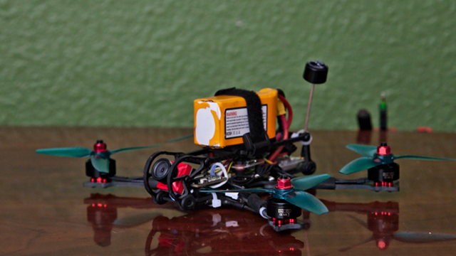
What the heck is up with this blog post? Did I already write about designing my HD micro quadcopter frame? Isn’t it already finished and nearly ready for production?
Yes. This is all true, but I was thinking about creating a video talking about all the early design decisions that shaped the layout of the Kestrel. I don’t know if I could do a good job talking about all this stuff without at least a loose script.

I don’t know how to write a script. I have a decade of experience writing blog posts. So here we are!
Everything goes back to McMaster-Carr
I like simple sandwich frames. Four arms with a bottom plate and a top plate separated by aluminum standoffs. It is a simple design. It works quite well. It is versatile—if your stack doesn’t fit, you can just use taller standoffs!
There are dozens upon dozens of sandwich-style micro quad frames. I don’t need to design one. They’re already everywhere!
The most innovative 3” frame I know of is the Ummagawd Acrobrat. The Acrobrat isn’t the frame for me, though. I wanted something lighter. I wanted individual, replaceable arms. I wanted arms for both 3” and 4” props. I also wanted to design something myself, so why not design exactly what I want to fly?

I needed rubber bushings for my suspension. I thought about buying some Acrobrat bushing kits, but they seemed expensive, and they would make it difficult to sell my own frame kits. So I went to McMaster-Carr.
I found a rubber grommet with reasonable dimensions. It would plug a hole in a piece of material 1/8” thick. That’s just barely thicker than a 3 mm piece of carbon fiber.
This is where the design work began. If my grommets fit into a 3 mm sheet of carbon, then the Kestrel’s side plates are going to be 3 mm thick.
When the grommets arrived, I reached for my 3D printer. Carbon fiber is thin, so you need to turn that round bushing into an oval. How tall and wide is does that oval need to be? I printed a variety of holes and tabs to get an idea of where to start. It wasn’t perfect. It needs to be snug, but not tight. The grommet needs to absorb vibrations, but not jiggle around.
This testing made it obvious that I needed to use 2 mm carbon for the Kestrel’s bottom plate. Any thinner, and my bottom plate would be too weak. Any thicker, and my soft suspension wouldn’t work very well!
Mounting your electronics
I wanted to make room on the bottom plate for three 20x20 stacks. Running your motor wires is easier if your 4-in-1 ESC board is in the center, so I knew I would have a stack right in the middle.
To keep the props out of view, the FPV camera needs to be way out in front. That left me plenty of room for a second 20x20 stack up front.
I’m trying to maintain balance, so why not stick a third stack in the rear and have a long fuselage? That might help offset the weight of the camera that has to stick out so far in the front.
That was enough thinking to get me through my first two prototypes. When I wanted to build my first 4” Kestrel, I realized that some ESC boards with 20x20 mounting holes are huge, so I needed to move the front and rear stacks farther away from the center.
I’m jumping ahead a bit, but I also realized that four of the bolts I was using to attach the Kestrel’s arms were quite close to being spaced correctly for mounting 30.5x30.5 parts from 5” and larger quads.
I haven’t used this option in any of my builds yet, but it was a simple change to make! The Kestrel has room for a 20x20 stack in the front and rear, and either a 20x20 or 30.5x30.5 stack in the center.
From 8 screws to 4 screws for mounting the arms
Using replaceable arms was a must. The Kestrel is open source, and the OpenSCAD source code makes it easy to configure arms in any way that you’d like. Do you want stubby arms for 2” props? Do you want ridiculous 6” arms? All you have to do is input different lengths and angles for the arms, and you’ll be all set to have a fresh set of arms cut!
My goal is to have the fuselage of the Kestrel be as static as possible. So far, I have cut 3” and 4” compatible arms, and those same arms will fit any of my Kestrel fuselages. I expect there will be a 5” experiment in the near future, too!
On the first few prototypes, I took the easy way out. Each arm was attached to the frame with a pair of M3 screws and lock nuts. This worked just fine, but when I decided that I wanted room for a full-size stack in the center, half of those screws were going to be in the way.
This was easier than I expected! The gap between the bone-shaped wedge and the arms is defined by a tolerance variable. I cranked it up from 0.025mm to 0.5mm to make it easier to see how it all fits together!
— Pat Regan (@patsheadcom) March 9, 2019
Next up is massaging the weight-saving cutouts near the mount holes. pic.twitter.com/vLT0RnY6kn
I eliminated one screw from each arm, and I replaced it with an I-shaped piece of carbon fiber—the wedge. The wedge keeps the arms from rotating forward and backward around the M3 mounting screws, and the 2 mm bottom plate and 1 mm bottom bracing plate keep the wedge from falling out.
This saved nearly three grams of weight, made the arms easier to replace when they break, and the arms are just as solid and sturdy as they were before!
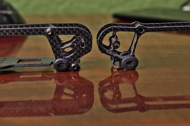
My first broken arm
I’m trying to save weight wherever I can. If there’s material that serves no useful purpose, it needs to go. There are two round cutouts near the base of each arm. One of those cutouts leaves you room to put M2 or M3 screws into your center stack.
The other cutout is to save the tiniest amount of weight. It seemed like a great idea. In a crash, most of the stress on the arm will be at the M3 mounting screw, right? How much stress could there be on that tiny length of material from the M3 screw to the wedge?!
This mistake seems so obvious with the benefit of hindsight. In some crashes, most of the force will be pushing the arm against the bottom plate or the brace plate. If you hit an arm while traveling parallel to the bottom plate, though, the arm acts as a lever around the M3 screw.
I broke an arm on my 4” Kestrel right at that weak spot.
It was easy to fix the design. If you’d like to watch, I walked through the design process on YouTube. All I had to do was put that piece of material back in. I imagine the arm is going to break somewhere completely different next time!
Everything is a tradeoff
Most of the time, I expect the tradeoff to be related to cost or time. With a quadcopter, the design decisions are almost always trading weight for durability. Carbon is cheap. Weight is problematic.
The first fuselage that I cut on my Shapeoko was fat. The side plates are 3 mm wide, because that’s how thick the material is. How thick do they need to be? I took a guess. It looked reasonable on my screen. That first prototype was so sturdy that I couldn’t flex the assembled fuselage at all!

The goal is to make the Kestrel just sturdy enough to survive most impacts, but no sturdier. I knew after assembling that first fuselage that my instinct to err on the side of being too sturdy would be a mistake. I don’t have fancy software to analyze the weak points of the Kestrel. I have to built it, fly it, and see where it breaks. That’s the best way for me to find the weak spots!
Convenience is also important
I imagine there’s quite a bit of weight to be saved by eliminating the rear 20x20 stack. Sure, I’d have to make the fuselage a little taller. The side plates are extremely long, so they have to be rather durable to resist flexing.
Is saving five or six grams worthwhile? For my builds, I don’t think it is. Spreading out the components makes the Kestrel easier to work on. That long body gives me plenty of room to mount a tiny GPS module up high in the back. I wind up putting the ESC and FC in the center and the Caddx Turtle board up front.
I can save weight by mounting a 200mw 20x20 VTX in the back, but there’s plenty of room back there for a 1,000 mW RaceDayQuads Mach3 VTX back there. Even with the GPS module.
More than a year ago, I help Brian build a 3” micro quad with a Runcam Split. It was awful to work on. It only had one stack with an ESC, FC, VTX, and both Runcam Split boards all piled up on top of each other. Then we had to find room to fit the R-XSR. Not only that, but all these boards had to be wired to each other. It was a mess.
Spreading things out makes maintenance so much easier!
What’s next? Why haven’t I ordered a batch of these so I can sell them?!
I have absolutely no idea how many frames to order. I’m not a store. I’ve never had anything manufactured for me before. I have no idea what I’m doing.
I was talking to Brian last night and today. We’ve run three quadcopter build classes at our local makerspace. The first time, the class built five or six 450 mm quads. At the second, we built six of my PH145 quadcopters. At the last class, we built six 5” FPV freestyle quads.
Things have come a long way since our last build class, and we think we can help get people started even more cleanly than before. Buy a Taranis radio. Practice in the simulator. Buy a Tinyhawk. Have fun. If you’re enjoying yourself, and you want to go farther, we’ll help you build a 3” Kestrel with an HD camera.
Outside of the parts list, we haven’t really hammered out any details. Maybe I’ll cut the frames for the class in my garage. That sort of thing is cool if the class is being held at a makerspace! Maybe the class will use the first batch of production Kestrel frames from CNC Madness. We’ll see!
Conclusion
All our Kestrels are flying great, except for my poor 3” Kestrel. She’s needed lots of extra filtering ever since the crash that burned out her first Caddx Turtle. I’m thankful that this isn’t the fault of the frame! I expect to upgrade her to the same parts we use in our upcoming Kestrel build class!
The arms are stronger than ever, and I think she’s just about ready to go into production. What do you think? Should I send the CAD files off to CNC Madness and have a batch of frames cut? How many do you think I need to order? Let me know in the comments, or stop by the Butter, What?! Discord server to chat with me about it!