I am excited! Frame design is going well. The Shapeoko is doing a fantastic job cutting carbon fiber. The first prototype of the Falcon is flying well, and I’m quite pleased that I’ve uploaded another open-source miniquad frame for the world to enjoy.
There were some minor issues with [the first prototype][]: some holes were too small, the inner arm mount screws are inconveniently spaced, and the carbon fiber plate shifted while cutting the arms.
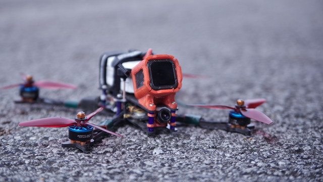
I was able to pause the CNC machine, then reposition and lock down the carbon fiber, and resume the cut where it left off. It looked like I got the plate lined up pretty well, but it was off by enough that I couldn’t mount the arms. Some filing fixed that, but I didn’t get to test the Kestrel-style arm wedge. Instead, I used two screws per arm.
- I Bought a CNC Machine: I Have No Idea What I’m Doing at patshead.com
- Cutting Carbon Fiber Sheets on My Shapeoko CNC at patshead.com
Changes since the prototype
I feel that I should mention that the prototype Falcon frame is flying great. There’s a slight measuring guesstimate error on my part that lets you see some of the top plate in the FPV video feed. Aside from that, I don’t think I’d be able to tell you whether I am flying my Falcon or Flowride in a blind test.
I was a combination of happy, surprised, and relieved that the battery strap locations on the Falcon were almost perfect. I’m using the same model for the top and bottom plate, so I have to rely on the slots in the center of each stack for battery straps. I was worried that this would position them in an awkward location.
The fuselage is shorter
As I was assembling the prototype, I realized that I had a lot of room between the FPV camera and the ESC board. I took a guess as to how much room the 20x20 stack in the front would require, and I guessed a little high.
I was worried that pushing the front and rear stacks closer to the center might goof up my battery strap locations. To check my work, I printed the full-length and partially-truncated top plates on paper. On a laser printer. Can you believe it?!
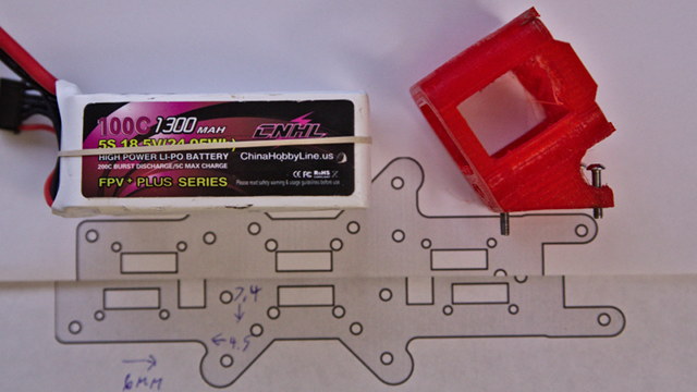
I wound up bringing each stack 5 or 6 mm closer to the center. My builds have the ESC power lead going out the side of the quad, but there’s plenty of room if you prefer to point the power lead towards the front or back of the quad. I tested this by putting spare ESC, an old 20x20 flight controller, and a busted Caddx Turtle on the paper.
This gave me a chance to check where the battery straps would land on the full-length frame. I don’t want to fly the full-length frame, so I’m happy that I didn’t have to cut one for testing! The battery straps line up great, and the battery sits in a good position.
While I was editing the top and bottom plates, I added a pair of cutouts around the center stack that can be used if you want to fly with your battery mounted in the toilet-tank style. I’m not sure if the exact center is the ideal spot for that, but I figured it couldn’t hurt to add the option. Especially since it saves a bit of weight!
- Kestrel and Falcon source code and CAD files at Gitlab
- My Open-Source FPV Freestyle Miniquad Frame: The Falcon at patshead.com
- The Kestrel HD Micro Quad Frame Version 1.0 at patshead.com
The arm brace plate holes are fixed, and the mount points are wider
I left holes in the bottom brace plate that were supposed to be big enough to fit a 2mm hex driver. These holes are there to allow you access to your stack screws. I goofed. They were too small for my tool. This has been fixed.
When testing the fitment of components on my printout of the bottom plates, I noticed that the central arm mounting screws would be almost directly underneath the ESC power leads if you chose to orient the ESC towards the front or back. This seemed dumb.
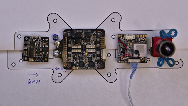
First, I moved the outer four arm screws farther from the center. Then I moved the inner screws closer to the sides of the fuselage. They now clear my Holybro Tekko32 ESC power lead by about 2mm.
This new layout results in a wider fuselage and shorter arms. It isn’t a huge difference, but this winds up trading a short length of 4mm carbon for two short lengths of 2mm carbon. It is probably a wash, but my gut tells me that it will make the frame less likely to resonate. I’m no expert, though!
The arms got longer, too!
The arms have a sort of L-shape to them. They come into the fuselage, then make a sharp turn at the first screw. If you imagine that screw as the fulcrum of a lever, you’ll see that this isn’t the best setup.
For arm rigidity, the best place for the second screw would be along a straight line that goes through the motor and the first screw.
We could share a screw with the 30x30 stack in the center, but that transfers vibrations to the flight controller. We don’t want to do that.
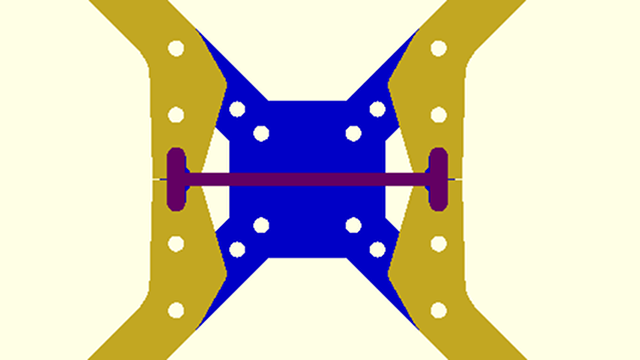
I could put an extra screw hole in each arm. If you’re using a 30x30 flight controller, you could lock the arm in with a screw through the 20x20 stack holes. If you break an arm, this will be awful. Your electronics will be in the way of the screw!
Every frame makes compromises. You need to choose your frame based on the compromises that matter most to you. This is one of those compromises. I want to be able to easily swap arms in the field.
I decided to extend the base of the arm closer to the center of the quad. The sandwich of the bottom plate and brace plate will still keep the arm locked in place. Probably not quite as solidly as if we had a screw through there, but it should be an improvement!
- Kestrel and Falcon source code and CAD files at Gitlab
- My Open-Source FPV Freestyle Miniquad Frame: The Falcon at patshead.com
- The Kestrel HD Micro Quad Frame Version 1.0 at patshead.com
Should I keep the Kestrel-style dogbone wedge?
I haven’t taken the wedge out of the design. The weight is negligible, and I bet it will make the arms more rigid, even if I have to use two screws per arm. The wedge is the part that allows me to get away with just a single screw for each arm on the Kestrel.
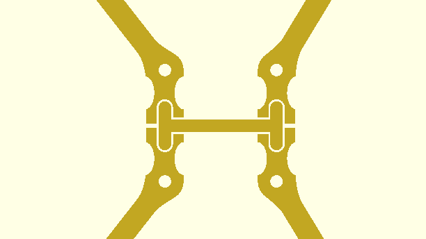
This works great on the tiny Kestrel, but I’m not convinced that the Falcon would be sturdy enough with just four screws holding the sandwich of arms together. I couldn’t test this on the first prototype, because of the mishap while cutting the arms.
For now, I’m leaving the wedge in the design. It will be easy enough to test when I cut the next prototype. I can just leave the inner arm-mount screws out of my build, and see how it feels!
- Kestrel and Falcon source code and CAD files at Gitlab
- The Kestrel HD Micro Quad Frame Version 1.0 at patshead.com
The arms still need a weak point
I’m writing about this as a reminder for myself. The Falcon’s arms are 12mm wide from the base to the motor mount. This could be problematic in a bad crash.
I’ve seen this happen on Brian’s FlosStyle. His arms have cracked right at the motor mount. He’s had to replace motors, because the carbon crushes the motor wires into the motor bell. I’d like the arms to break somewhere else!
I plan to put some sort of taper on the arms, so they will be a little wider near the motor mounts.
Making room for the DJI FPV Air module
The DJI FPV Air module is huge. The width isn’t too bad, but that sucker is long, but I think I’ve come up with an interesting way to make room for it.
No matter what I do, the DJI module is going to require a longer fuselage. There’s just no way around that, but I’d like to use every trick I can think of to keep the front end from sticking out too far. Even with a DJI FPV module, I would still want to run a GoPro, and you don’t want all that weight sitting too far forward!
What if I replace the arm brace plate with another bottom plate? That would move the DJI module lower by 6mm.
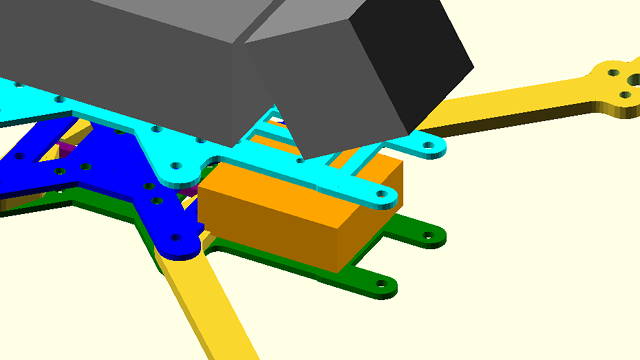
Your FPV camera tilts upward, so the bottom of the camera sits farther forward than the top. If I move the Air unit 6mm lower, maybe the camera will fit without pushing it forward?
I’m going to keep puzzling this out. It will definitely require at least one new bottom plate. This one will need to include only the rear and center stacks. I hope I can fit the Air module and its FPV camera without extending the front end too far forward.
I’m pretty confident that the DJI module would fit in my prototype frame, especially if I had that extra 6mm of vertical clearance. Maybe I will be undoing some of that fuselage-shorting work?!
- Kestrel and Falcon source code and CAD files at Gitlab
- My Open-Source FPV Freestyle Miniquad Frame: The Falcon at patshead.com
- The Kestrel HD Micro Quad Frame Version 1.0 at patshead.com
When can I buy a Falcon frame?
The most likely answer is that you’ll never be able to buy a frame. I’m not a manufacturer. I don’t know where to have quality carbon fiber cut for a good price. I’ve heard good things about CNC Madness in Canada, and I’ve gotten rough quotes from them for cutting my Kestrel frame.
Their prices are fine in quantity. They offer good service. They gave me a quote for a single frame and for a large enough quantity to get down to their lowest bulk-order pricing.
Even at their lowest price per frame, you would have to pay me roughly the price of an Ummagawd Acrobrat for me to make a small profit and still feel safe enough to make the attempt. If I remember the pricing correctly, you could order one of my Kestrel frames from CNC Madness for almost $10 less than the price of an Acrobrat.
Oh good. We are up to the fun part of the cutting job! All the boring holes are drilled, and now we are cutting out the perimeter! pic.twitter.com/n9RVeD4mDp
— Pat Regan (@patsheadcom) July 20, 2019
The Kestrel is unique. It is heavily inspired by the Acrobrat, but it fills a different niche, so I am still exploring the idea of finding a way to have it manufactured.
My Falcon frame isn’t unique. I’ve borrowed ideas from all my favorite frames. There’s a little bit of Hyperlite Flowride, FlosStyle, and Glide in my Falcon. I don’t think you should buy my frame when one of those three frames will probably meet your needs.
The only unique feature that I might be offering is the lowered deck specifically engineered to hold the DJI FPV module. I won’t be surprised if I get the CAD files to cut a Falcon frame that fits these big modules up on Gitlab before similar frames hit the shelves, but it won’t be long before this is a common feature.
- Kestrel and Falcon source code and CAD files at Gitlab
- My Open-Source FPV Freestyle Miniquad Frame: The Falcon at patshead.com
- The Kestrel HD Micro Quad Frame Version 1.0 at patshead.com
If you can’t sell frames, why are you designing them?!
I’m having fun. That alone is more than enough reason for me to be doing this. I’m also excited about sharing my work with the community. My frames are all open-source. If you want to cut your own, you can. If you want to manufacture them, you can.
There is one feature that the Falcon and Kestrel share that I haven’t seen in any other frames. The designs are parametric. That means that all the angles and dimensions are clearly defined in the source code.
It is easy to accidentally make a terrible parametric design. I have plenty of OpenSCAD programs that went off the rails, and tweaking the core parameters winds up making the model come out all weird and wrong.
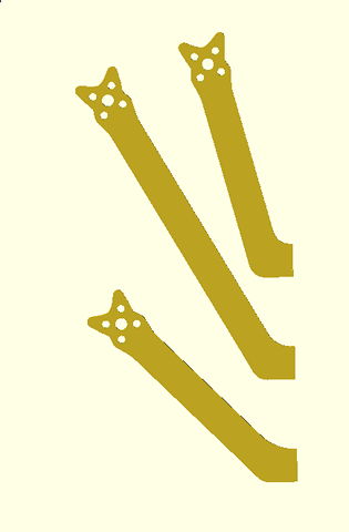
I was careful with both the Falcon and Kestrel. The important parameters all work well for any reasonable range of measurements. If you want to run 7” props on a Falcon, you can simply increase the length of the arm by around 13mm. If you want a stretch-X Kestrel, you can make the arms longer and adjust the angle. If you want to put huge 2508 motors on your tiny Kestrel, you can tweak the measurements of the motor hole spacing, and the end of the arm will scale itself up.
Even if I don’t think the Falcon is unique enough to manufacture, I think there is a lot of value in having the ability to quickly adjust the dimensions of the frame to suit your needs.
Conclusion
I’m excited. I hope that is obvious. The Falcon has seen a lot of small improvements since cutting the first prototype, and I expect it to see at least a few more improvements before I cut another one.
I’m not in a hurry! I need to fly the first prototype more. More importantly, I need to crash the first prototype more! Seeing where it breaks will be of tremendous value!
What do you think? Am I doing a good job? Would you like to fly a Falcon or Kestrel? Do you think I’ve made any serious mistakes?! Let me know in the comments, or stop by Butter, What?! Discord server to chat with me about it!
- Kestrel and Falcon source code and CAD files at Gitlab
- My Open-Source FPV Freestyle Miniquad Frame: The Falcon at patshead.com
- The Kestrel HD Micro Quad Frame Version 1.0 at patshead.com
- I Bought a CNC Machine: I Have No Idea What I’m Doing at patshead.com
- Cutting Carbon Fiber Sheets on My Shapeoko CNC at patshead.com